

Introduction: Music Reactive Desk Lamp


Hi! In this instructable we'll be building a good looking light that dances to all sounds and music, using simple components and some basic Arduino programming. It makes an awesome effect while standing on the desk when gaming, playing music, and anything else that makes sound really. Let's get going!
Attachments

Step 1: Main Supplies

First things first: what kind of supplies do we need and what do they cost? Well, they are largely optional, and can be made with much improvisation. Even so, some key items are needed if you want to follow this guide:
- Arduino Nano (or any equally small Arduino type) (3$ buy link)
- Sound Detector Module (1$ buy link)
- 5 volt power supply (or 12 volt with this stepdown module, as I'll be doing it here)
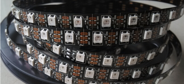
- Individually Addressable LED strips 60 leds per. meter (buy link)
Depending on the look you want, you might want to arrange the strips differently or diffuse the light in another way. This is where you can be creative. If you like my approach, I used the following items:
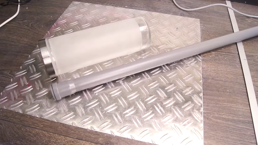
- The tallest IKEA Droppar jar (IKEA Link)
- A small length of PVC pipe.
All things considered I spent around 30$, where the LED strips were by far the most expensive part.
Step 2: Powering the Components


The star of the show is the sound detector module. This will provide an analog signal to the Arduino, which we can use to (hopefully) cleverly light the RGB lights. To be able to do this, we need to power both devices. Luckily they both require a 5 volt input. I am using a step down module to step down from 12 volts to 5 volts, but it would be easier to use a 5 volt power source directly. Wire the VIN on the Arduino and on the sound detector board to the positive input. Then wire the GND on the Arduino and the detector to the negative. Look at the black and the red wires on the attached schematic. We also need to hook the positive and negative input on the LED-strip to the power source.
Step 3: Detector & Strips


After having connected all three parts to the power, we need to connect them to eachother.
The sound detector module will communicate with the Arduino over the analog input pins. I will be using pin number 0, but which one does not matter.
The LED strips need a digital pulse to be able to understand which LED we want to address. Hence we need to connect a digital output pin to the Arduino nano. I will using pin number 6.
Awesome, now we are mostly done with the electronics!
Step 4: Uploading the Code
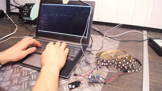

The most important part of this build will arguably be the code. It can change this build from pretty cool to insanely awesome. You can find the code i used here (github link). The main principle is to map the analog value we get from the sensor, to an amount of LEDs to show.
We can do this using the map function. This will let us display a certain amount of LEDs given an input, but nothing more than that. Doing only this might give you a jittery and flickering light. I decided to operate on the average of the llast X amount of readings to create a more sane and smooth transition. I also did some more advanced tracking of the song/sound intensity based on averages, to let the light change colors when the song enters a peak.
I will answer questions about the code if you have any, it's far from done, and contributions are welcome!
Step 5: Did Anyone Say Stuffing?


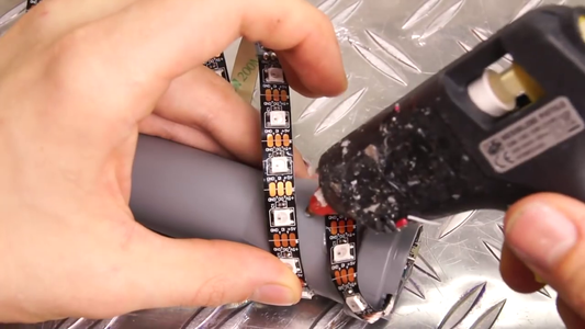

With all the code and the components done, it is assembly time. The PVC is obviously hollow, and we will take advantage of that by stuffing the electronics on the inside. We'll cut a slit in the PVC pipe to let us slide the strip out without obstructing the flush surface of the PVC hole. After that, we can glue the LED-strip to the PVC pipe. Some have asked me why I used hot glue, and not only the adhesive on the back of the strip. It's simply because my experience with it is that it will hold fine on really clean and straight surfaces, but on a curvature like this it will most likely let go in a matter of days. Hence: hot glue!
Step 6: The Container Itself

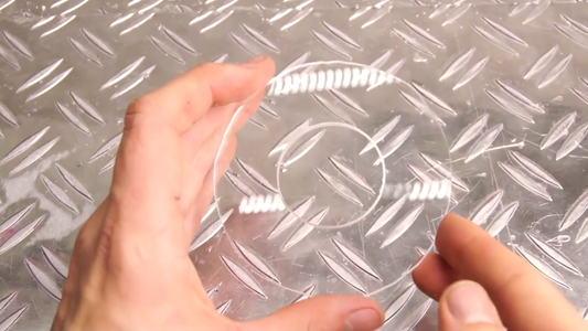


First I thought the lid was made out of acrylic, so I tried to drill a hole in it. Turns out it was made out of glass, and it broke. Clever! So, that's why I'm cutting out a sphere of acrylics with the same diameter as the lid, with a hole equal to the size of the PVC pipe in the middle. It turned out pretty cool, and I love the shine of new acrylic. Before putting on the frosted IKEA jar, we have to glue the stick of LEDs to the lid.
Step 7: Finishing Up!


We can see by the hole, and the placement of the electronic components, we can reach both the Arduino USB interface and the power input from underneath. I took a little shortcut on the legs, and used some potentiometer knobs I had lying around. Ideally you want some nice wood or maybe some turned aluminum?
Step 8: Done!

This was a great project, and I love it especially because it is so customizable and updatable in the future. I encourage you to look at the video in the top for the actual results. If you don't want the instructions, you can skip to the end to see the action.
Thanks for reading through, hope it was worth your time.
Hansi

Second Prize in the
Arduino Contest 2016

Participated in the
Epilog Contest 8

Participated in the
Make it Glow Contest 2016


