

Introduction: NaCade - the Naked Raspberry Pi Arcade Machine


Who doesn't like gaming? Having grown up playing arcade machines, as a kid you could only dream of owning one. Now with advances in technology, gaming is available to everybody. Sure, there is plenty consoles and handheld units even smartphones to choose from but what I wanted was the nostalgic feel of a standup arcade without the need for a large room to put it in. Oh yes and portability is pretty handy too.
Step 1: The Main Components
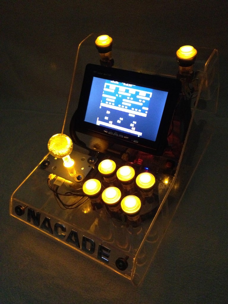

The brains of this setup is the Raspberry Pi computer. It's not overly powerful by today's standards but it can run early style games and systems pretty well. It's small size and low power consumption makes it ideal for many different uses. Best of all it's cheap to buy. The software comes courtesy of Shea Silverman's PiMAME http://pimame.org It has a bunch of great gaming emulators built in.
The display is an ordinary 7" LCD (car reversing monitor) which is sufficient enough for these low resolution games although the menus can be a bit too small to read. I had to use a larger monitor when I set it up initially. Working with scripts on this screen was impossible though a 9" screen would be a better option if I had to do it over.
The AV input on the screen is connected into the yellow RCA port on the Raspberry Pi.
I used an arcade quality joystick and illuminated buttons which are wired directly into the Pi. Power is supplied through an 9 amp hour AGM battery which is charged by an inbuilt 15amp solar controller. The solar controller regulates voltage from an external source which in this case is a solar panel. Yes, its powered by the sun!
Sound comes from a portable USB speaker that has its own internal battery.
The box itself is made from 3mm clear acrylic and as it was my first attempt working with plastics, I spent a lot of time researching how to cut and bend acrylic sheets with the helpful guides available here on Instructables.
Step 2: Parts

- 3mm Acrylic Sheet 1200mm x 1200mm - $50 (Local plastics supplier)
- 7" LCD screen (car reversing display) - $40 (http://www.ebay.com.au/itm/300881733887?ssPageName=STRK:MEWAX:IT&_trksid=p3984.m1423.l2649) - but I would recommend using a 9" screen or a better quality (http://www.ebay.com.au/itm/9-TFT-16-9-Car-Rear-View-Reverse-Camera-DVR-LCD-Screen-Color-Monitor-Display-/400554061185?pt=AU_Car_Parts_Accessories&hash=item5d42e1ed81&_uhb=1)
- Raspberry Pi model B - $40 (http://au.element14.com/jsp/displayProduct.jsp?sku=2191863&CMP=KNC-GOO-COM-RPI&mckv=svFQl3BNG%7Cpcrid%7C24644018808)
- 16gb SD card - $15 (http://www.ebay.com.au/itm/SanDisk-16GB-Ultra-UHS-I-SD-HD-Video-16G-SDHC-Memory-Card-Extreme-Fast-Class-10-/230950599191?pt=AU_Electronics_Memory_Cards&hash=item35c5ba7a17&_uhb=1)
- 15 Amp solar controller - $15 (http://www.ebay.com.au/itm/15A-12V-24V-Solar-Panel-Battery-Charger-Controller-Regulator-/190893022116?pt=AU_Solar&hash=item2c721c5ba4&_uhb=1)
- 9 AH 12V AGM battery - $35 (http://www.ebay.com.au/itm/9AH-ALARM-BATTERY-AGM-SLA-DEEP-CYCLE-UPS-12-VOLT-POWER-SUPPLY-SPOT-LIGHT-7AH-/300859124528?pt=AU_Electronics_Batteries_Chargers&hash=item460c99eb30&_uhb=1)
- 12V USB converter (Kensington PowerBolt Duo) - $20 (http://www.ebay.com.au/itm/A51-New-Kensington-PowerBolt-Duo-USB-2-1-Amps-Car-Charger-for-iPhone-iPod-iPad-/231038512927?pt=US_Tablet_eReader_Chargers_Sync_Cables&hash=item35caf7ef1f&_uhb=1
- USB powered speaker - $35 (http://www.ebay.com.au/itm/MOSHI-tm-BASSBURGER-BASS-BURGER-MINI-SPEAKER-BLACK-BRAND-NEW-/171101015097?pt=AU_Electronics_Portable_Audio_Accessories&hash=item27d66a4c39&_uhb=1)
- Arcade joystick and illuminated buttons - $50 (http://www.austinamusements.com.au/joysticks/yellow-illuminate-joystick-12v/prod_275.html)
- assorted switches - $10
- wiring and socket - $10
- GPIO breakout board and cable - $9 (http://www.ebay.com.au/itm/GPiO-Breakout-for-Raspberry-Pi-Breadboard-Cobbler-/171104007671?pt=UK_BOI_Electrical_Components_Supplies_ET&hash=item27d697f5f7&_uhb=1)
- 20w mono solar panel - $40 (http://www.ebay.com.au/itm/New-20-Watt-12v-Monocrystalline-Solar-Panel-20W-/330976676829?pt=AU_Solar&hash=item4d0fbf4bdd&_uhb=1)
- Another 12v USB charger for the speaker - $1 (http://www.ebay.com.au/itm/Universal-Mini-USB-Car-Charger-Adapter-Black-Auto-Charger-DC-12V-/321120087244?pt=AU_MobilePhoneAccessories&hash=item4ac43faccc&_uhb=1)
- Assorted bolts and nuts
- clear rubber adhesive feet for the base (Local hardware store)
Step 3: Tools Required

- Heat gun or a strip bender
- scroll saw
- holesaws and drill bits
- scoring knife, straight edge and a ruler
- soldering iron
- wire strippers
- clamps
- metal file and sandpaper
- screwdrivers
- masking tape
- acrylic glue
Step 4: Planning

I'm not good at sketching out designs so I used some cardboard to make a mockup box. I could get a feel for the spacing and layout of the controls much easier like this. The final width of the unit was determined by the controls and the screen. Everything else had plenty of room to fit in.
Step 5: Building the Box

Once the cardboard mockup is sorted, its just a matter of pulling it apart again and using it as a template by laying it flat against the sheet of acrylic. All the bends are marked in their positions and the holes traced out. The mockup can be put back together for later reference. The important part is the main body (which holds the screen and controls) that wraps all the way round.
The two side panels can be marked out and cut once the main body has been shaped.
Step 6: Cutting the Sheet

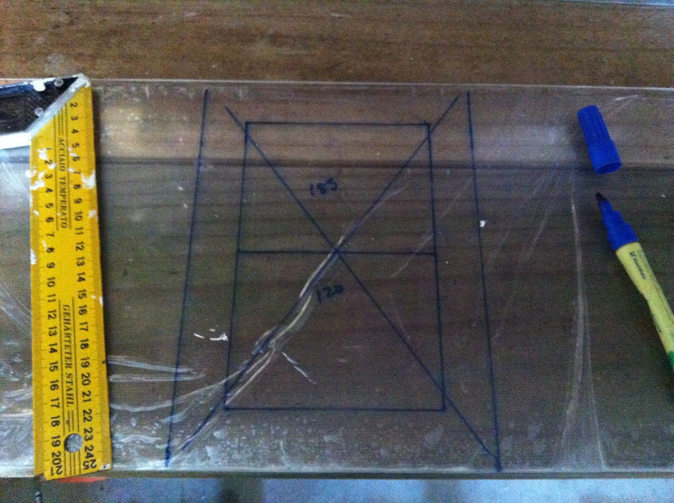
For the main body I needed a long strip of acrylic. To get a nice, straight cut I used the score and snap method. It involves using a straight edge and a scoring knife to mark the sheet deep enough so when downward pressure is applied it snaps exactly where it is needed.
The holes for the joystick and buttons are cut out with a holesaw. The trick is not to rush and allow the drill to gently cut through.
Step 7: Bending the Sheet


After a few practice runs on some offcuts, I found setting the heat gun on 250 degC gave the best results without melting and bubbling the sheet. The sheet is clamped with a straight edge then gentle even pressure is applied as the acrylic becomes soft. It takes time and patience but it can be done.
Step 8: Controls

After the main body is made up the buttons and joystick is added along with the power button. With access from the sides wiring is easy to hook up at this stage. All the switches are linked to a common ground pin on the Raspberry Pi GPIO board and the trigger signals are individually wired to their own GPIO pins respectively.
Step 9: Side Panels


The side panels are made from templates by tracing around the edge of the main body. Once cut, the side panels are then glued into place with fast set acrylic solvent which 'welds' the acrylic together and forms a very strong bond.
Step 10: Adding the Components


With the side panels now firmly glued on, the cut-out for the screen now becomes the main access inside the box so some adhesive velcro is used to make it easy to remove the display. Acrylic rod is cut down to make standoff legs on the circuit boards so they stay on the floor of the case. Its a tight squeeze but having the clear panels help make it easier to see inside when adjusting and fiddling with the wiring. There is enough room for all the circuit boards to fit as I removed the solar controller board from its box to save on space.
It can get a bit messy with the wiring so I added some split convoluted tubing to neaten things up a bit.
Step 11: Wiring


Being a 12v system, the unit is a fairly basic to wire up. The solar controller is the hub where power is directed from a charge source to the battery and then to the load so power comes in and goes out through this hub. Fuses have been added in between the positive wires for protection.
The Raspberry Pi gets its power from a Kensington Powerbolt duo car accessory adapter as it supplies stable 5v power. I've added another 12v to 5v charger for the USB speaker so I can control its charge with a switch in the back of the unit. This cuts the power when it has reached full charge (tends to make strange clicking noises).
The 9AH sealed battery is heavy at almost 3kg but has an ample amount of reserve capacity. The system running draws about 900mA which easily gives over of five hours of runtime.
Step 12: Joystick and Buttons


The GPIO cobbler board allows the controls to be hooked up to the raspberry pi directly. Without going into too much detail because I'm no expert, the on/off signals from the controls are seen by the raspberry pi and with a programming script, the signals are mapped to specific keyboard functions so the controls act as a keyboard emulator. Adafruit have an excellent guide here http://learn.adafruit.com/retro-gaming-with-raspberry-pi/buttons.
It was a lot of trial and error but in the end I used this script which I modified to suit my button layout https://github.com/adafruit/Adafruit-Retrogame/blob/master/retrogame.c.
Here is my script change at line 87
// Input Output (from /usr/include/linux/input.h)
{ 22, KEY_LEFT },
{ 2, KEY_RIGHT },
{ 4, KEY_UP },
{ 3, KEY_DOWN },
{ 27, KEY_C },
{ 23, KEY_X },
{ 11, KEY_Z },
{ 24, KEY_A },
{ 10, KEY_S },
{ 9, KEY_D },
{ 7, KEY_5 },
{ 8, KEY_1 },
{ 25, KEY_ESC }
};
Each line in this table contains two elements. The first is a GPIO pin number (where a button or one direction from a joystick is attached), the second is the corresponding key code to be generated by this control. A list of valid key code names can be found in the file /usr/include/linux/input.h starting around line 178. Remember to enclose each pin/key pair in {curly braces} with a comma between them. Basically the controls can be programmed to do the job of any key on a keyboard.
Step 13: Program

To install PiMame on an SD card in Windows, you need to download an image burner such as Win32 Disk Imager. After you have PiMame downloaded, you should be able to extract it to view the PiMame.img file. Launch Win32 Disk Imager and under "Image File", select the PiMame image. For "Device", select the drive letter for your SD card. Then click "write" to burn the image to the SD card.
For Mac computers you do not need any extra software. Just download the PiMame zip file and extract it. Insert your SD card and open up a terminal prompt. Type in "df -h"
Record all of the "disk" entries that are listed (ex. disks1). Go into your Disk Utility settings and find your SD card and unmount it (not eject). Then go back to your terminal prompt and type "df -h" again to see which disk is no longer there. The missing one is the disk ID of your SD card. With that in mind, type in this command
sudo dd bs=1m if=~/PATH TO PIMAME/pimame-0.5.img of=/dev/DISK#where PATH TO PIMAME is the path to where you downloaded the PiMame image and where disk is set to your SD cards disk number (ex. disks1 = disk1).
Executing this command will burn the image to your SD card. When it's done, you can type in
sudo diskutil eject /dev/DISK#
This will eject your SD card. Insert card into the Raspberry Pi and power it up.
Upon a successful bootup, you will be automatically logged in and the PiMAME main menu will appear on screen. From here you can access multiple emulators and utilities for the Raspberry Pi. Use the up and down arrows to navigate and press “Enter” or “c” to select an option.
All ROMs for the systems should be stored in the /home/pi/roms/ directory. PiMAME has a built in FTP server and web uploader that makes adding games easy. To access it go to the IP Address of your Raspberry Pi in a browser (you will need to have your Raspberry Pi connected to your network) and you will be greeted with the PiMAME web page and from there click on the “ROM Uploader” button
enter in your username and password. (Default: pi / raspberry)
you will now see your home folder so click on ROMS
click choose file and select the item you want to upload
click upload and wait for the transfer to complete
Using a file server like FileZilla https://filezilla-project.org is another way but it is more complex.
Mame4all uses 0.37b5 roms and advancemame uses 0.106 roms but some are not compatible so you will have to try each rom to see if it will work.
I spent more time on the software than building the box! I am no programmer just an ordinary car mechanic so I have learnt a lot from this project. This is a very helpful site for programming http://elinux.org/RPi_Beginners.
There is plenty to do to get all this working from installing the operating system to the configuring the controls but its definitely doable for even an amateur like me. I found it was always important to keep a backup up just in case so I wouldn't lose all my hard work.
This project was created with ideas and guides from various sources (experts of course) that are linked throughout this Instructable.


