

Introduction: Nerf Modding 101: Longstrike CS-6


Today I am going the show you how to do basic all-around beginner--intermediate modifications in the Nerf Longstrike CS-6
Warning: If performed incorrectly, modifications can reduce performance or render the blaster inoperable. When performing even basic mods, there is always a risk of losing parts, cracking plastic, or not being able to re-assemble the blaster. Some of the more common blasters' internal pictures can be found online, and it is worthwhile to use these as references.
When performing cosmetic mods, care must be taken in order to not lock up any moving parts. Without a few layers of a hard clear coat, paint can gum up areas where plastic slides on plastic. For more complex mods like barrel replacement and fabrication of sealed breech, you must take into consideration the volume of the plunger tube in relation to the barrel length, and spring power must also be increased. So make sure you know what you are getting yourself into before you start a mod.
Credit for and information in this 'ible was originally created, published, and copyrighted by Orange Mod Works™
Step 1: Introduction
In the first part of this 'ible I will show you how to do some mods for beginner modders, people who are doing something like this for the first time.
What is a Mod?
A modification or “mod” is anything you do to your blaster that changes its looks, form, or functionality. Doing a custom paint job, adding your own accessories and parts, and working on the internals to increase power are all considered mods.
Why Mod?
There are a plethora of reasons to mod a blaster:
• A modded blaster is a great addition to a costume.
• A blaster that you mod becomes your own work of art.
• A modded blaster can shoot further and with more intensity compared to FOF (fresh out of factory) blasters. It can give you the upper hand in your next battle.
• Cosmetic modding, when done right, yields stunning results. A humble foam blaster can become anything from a dystopian “steampunk” gun to a clean cut weapon right out of science fiction. They can even mimic weapons out of video games and movies.
Regardless of the reason, modding is an incredibly fun hobby that creates custom works of art out of average foam blasters.
Step 2: Chapter 1: Opening the Blaster


It is important to be familiar with your blaster’s internal structure in order to carry out any performance-related mods. Be sure to remember that there is often a variety of screw sizes in your blaster, so keep track of which screws go where. Make sure no small springs shoot out when the blaster is opened. The blaster should be unloaded with the mainspring relaxed. Try to avoid opening the blaster when it is in the cocked position, as it can shoot out the back of the blaster and cause injury.
Supplies Needed:
• #1 Phillips Head Screwdriver
• Small Flat Head Screwdriver
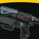
Step 1: Set Blaster on a clear workspace with the screws facing you. (Pic. 1)
Step 2: Remove screws. Be sure to make note of each screw's placement, because sizes differ. It is helpful to place the screws on the table in their original positions relevant to an outline of the blaster. Refer to the above picture for visible screw locations. The picture below demonstrates the different size screws and where in the blaster they go. (Pic. 2)
Step 3: Utilizing your screwdrivers (or a small enough hammer if you have one), pry one end of the priming handle off and remove the priming handle. (Pic. 3-4)
Step 4: At this point, the blaster should easily separate into two halves. If it appears to be sticking, double check to make sure that all the screws have been removed. If the issue continues, use a flat head screwdriver and gently pry around the seam until the blaster separates. (Pic. 5)
Set the top half aside, and you should have something that looks like this: (Pic. 6-7)
Step 3: Chapter 2: Removing the Locks


Locks allow you to half-cock your blaster, and are there to ensure that the slide is racked to the most rearward position before trigger is pulled. The magazine lock prevents the magazine from being removed unless the slide is pulled all the way back Many modders prefer to remove these locks in order to control blaster function precisely to their liking. Locks are geared towards the safety of younger users, and may be left in if desired.
In this chapter, we will examine each of the locks and what each lock's purpose is, so you can decide if you believe it is worth removing.
The first lock we’ll look at is the trigger lock. This prevents you from pulling the trigger while the bolt sled is pulled back. This can be removed by simply lifting the front, hooked part of the trigger up and pulling out the lock. (Pic. 1)
Step 1: Remove the rod connecting the magazine release switch and the actual magazine release. (Pic. 2)
Step 2: Remove the magazine release itself. (Pic. 3)
Step 3: Remove the magazine lock. (Pic. 4)
Step 4: Reinsert all components of the magazine release mechanism. (Pic. 5)
Observing the close-up photo of the internals in the last step, the large black piece is part of the mechanism that serves to allow the Longstrike to be half-primed. This is generally considered a safety mechanism for those who may not be quite strong enough to fully prime the Longstrike in one pull, so you may remove it if you feel it’s necessary. To do so, there are two additional components behind this piece that must be removed as well.
Step 5: Remove the two screws holding the lock in place, then take out the now loose parts and springs. (Pic. 6)
Step 6: To remove the final piece, we found it to be easiest to reach in with a pair of needle nose pliers, as it’s difficult to get in there with your fingers. (Pic. 7)
Your blaster will look something like this. (Pic. 8)
Step 4: Chapter 3: Air Restrictor Removal (Part 1)


The air restrictor slows down the flow of air from the plunger to the dart. This device serves to reduce the blaster's power and prevent the plunger from slamming into the plunger tubing at full speed, drastically reducing the noise generated during firing.
Note: Some of the plunger tubing pictured below has been cut out of the plunger for demonstration purposes.
Supplies Needed:
• Hammer
• Nail or small screwdriver or punch
• Pliers (optional)
Step 1: Remove the reinforcement plate by unscrewing it. (Pic. 1)
Step 2: Remove the mainspring. (Pic. 2)
Step 3: Remove the trigger catch. (Pic. 3)
Step 4: Now you can pull off the plunger and remove the bolt sled assembly. (Pic. 4-5)
Step 5: Remove the retention pin using your nail, small screwdriver, or punch. Separate the bolt sled and breech and put the bolt sled and retention pin aside. (Pic. 6-7)
The inside of your breech should look like this: (Pic. 8-9)
Tip: In the Longstrike, everything inside the plunger tube can be removed, but be careful not to drill into the walls of the tube. If you shake the plunger tube, you should hear some parts rattling around.
In the next section, I've listed 2 different methods for air restrictor removal. Please review the supplies required for each, and pick one that's most convenient for you. If done correctly, both of these methods will work. However, drilling is the easiest and most convenient method.
Note: The breech removal process is the same for each method and must be completed prior to starting on the next part.
Step 5: Air Restrictor Removal: Method 1


Supplies Needed:
• Drill
• Long 3/8” drill bit
• Gloves
(Pic. 10)
Step 1: Use gloves to hold the plunger tube and drill from the end that has the O-ring. It will take considerable pressure to get the bit to catch the plastic. Wearing a glove will prevent you from suffering a burn on your hand, should the bit catch the tubing and start to spin. If the tubing starts to spin. (Pic. 11)
As you drill, pause every so often to check your progress. When the spring and the three-pronged plastic piece has been drilled enough to fall free of the tubing, It's time to use the drill bit's sharp point to remove the post.
Step 2: Carefully drill through the center of the remaining plastic piece until the post falls free. If you think the bit has gone far enough, but the post is still hanging, use needle nose pliers to work it free. (Pic. 12)
Step 6: Air Restrictor Removal: Method 2


Supplies Needed:
• Pipe cutter
• Epoxy
• Permanent marker
Step 1:
Using your permanent marker, mark on your breech as shown in this picture. This will be wear you cut with your pipe cutter. This isn’t an exact science to this, so you’ll just have to eyeball it. (Pic. 1)
Step 2: Using the pipe cutter, cut through the breech. (Pic. 2-3)
Step 3: Separate the two halves, then simply shake out the contents. (Pic. 4)
Step 4: Using the epoxy, reattach the halves to each other.
Step 7: Chapter 4: Modifying the Plunger O-Ring


The O-ring seal on the plunger tubing makes sure the air compressed by the plunger assembly and spring does not leak out during compression. Some blasters come with an excellent O-ring seal while some come with undersized or loose O-rings. Improving this seal is an easy mod that can add a few extra feet to your shots. It is worth noting that the Raider comes with a superb stock O-ring, and does not really need modification.
Supplies needed:
• Small flat head screwdriver
• Teflon tape
• O-ring safe lubricant such as petroleum jelly or silicon based lubricant
Caution: Make sure whatever lubricant you use is safe for rubber O-rings. Lubricants like WD-40 will melt the rubber over time and destroy the O-ring. Lubricants like gun oil can penetrate the O-ring causing it to swell. This will cause the plunger to lock up inside of the plunger tubing rendering the blaster inoperable until the O-ring is replaced.
Step 1: Remove the bolt sled and plunger from the blaster (see Steps1 through 5in Chapter 4 for details)
Step 2: Remove the plunger from the plunger tube and gently pry the O-ring out of its groove with a flat head screwdriver. Be careful not to damage the O-ring if you plan on reusing it. (Pic. 1)
Step 3: This method involves wrapping a thin layer of tape around the O-ring lip in order to create a better air seal. You must take care not to use too much tape because it will create more pressure between the O-ring and the wall of the plunger resulting in greater resistance against the spring. When done correctly the plunger tubing should slide easily back into the plunger. Electrical tape is not recommended for the Raider, as it is too thick. It is also recommended to wrap the Teflon tape around the plunger only once. Make sure to wash off any factory lubrication before applying the tape because it will not stick otherwise.
When finished, it should look something like this: (Pic. 2)
TIP: You can also replace your current O-ring with a moderately thicker one for the same effect. (Pic. 3)
Step 8: Chapter 5: Modifying Spring Tension


Increasing the tension of the mainspring will give your blaster a small power boost by taking up the slack that is normally present. By swapping the mainspring with a more powerful one you can easily double the power of your blaster but over time powerful springs will increase the wear on the blaster.
Supplies Needed:
• Method 1:
• Aftermarket spring
• Method 2:
• Duct tape or electrical tape
Step 1: Method 1:
Utilize steps 1 and 2 in Chapter 3 to remove your mainspring, then replace it with your aftermarket spring. (Pic. 1)
The aftermarket spring picture above is made out of slightly thicker wire. The stock spring was measured at around 2.5 kg and the aftermarket spring was measured at over 6kg. The spring swap alone will allow the Raider to fire an angled shot up to 70 feet and can be found in the Orange Mod Works Stage 1 performance kit. (Pic. 2)
Step 2: Method 2:
Create a 1 cm wide buffer out of tape by wrapping it around the outside of the plunger where the spring would rest normally. (Pic. 3)
Make the tape layer thick enough to hold the spring in place but not thicker than the plunger lip. Be careful not to make the strip of tape too wide because you will not be able to cock the plunger back if it is. This mod gives you a boost in spring tension without having to stretch out the spring. Stretching the spring causes irreversible damage to the spring and will decrease its performance after only a few shots.
Step 9: Chapter 6: Easy Stock Removal


A common complaint regarding the Longstrike is the inability to remove the stock without disassembling the blaster. With this mod, you’ll be able to insert and remove the stock much more easily, as you can simply pull it directly out without the hassling of taking your blaster apart every time.
Supplies Needed:
• #1 Phillips Head Screwdriver
• Utility knife or other sharp knife
• Permanent marker (optional)
Step 1: Take apart the blaster as detailed in Chapter 1.
Step 2: Remove the two stock locks (use pictures 6-7 in Chapter 1). You can mark them with your marker where you’d like to cut them or not, but your goal is to make the teeth that hold the lock in place look like this: /\ , instead of this: |\ . (Pic. 1)
Step 3: Cutting as indicated should yield results like this. (Pic. 2)
Step 4: Reinstall the locks into your blaster and you’ll now be able to pull the stock directly out without taking the blaster apart.
Step 10: Chapter 7: Problems With Creating a Sealed Breech
With direct plunger magazine fed foam blasters such as the “Longshot”, a sealed breach similar to that of a firearm can be made out of tubing. This breech feeds each dart into a sealed chamber before firing. Because the blaster is firing from a closed breech it is able to achieve near perfect air seals plus the advantage of a long tight bore barrel. With the reverse plunger system found in this blaster the volume of compressed air needed to use a sealed breech to its full potential is not present and the size of the blaster is not ideal for adding a barrel.


