

Introduction: Smart Meeting-room Lamps! Never Miss a Meeting.


Just over three months ago, we at Mapiq moved to a bigger office. It was quite a step up from our last humble abode, having about five times the floorspace that we had before. We had some crazy ideas about how we wanted to use the space, but having a fancy, dedicated meetingroom was one of our top priorities. Only problem, meeting rooms become really dull, really fast. A big table, some chairs and a screen are part of the standard bill of materials, but we wanted something funky and interactive to spice up the room.
The company i work at builds software that runs smart buildings, and one of the things we do really well is roombooking. Usually we build integrations between existing hardware and our platform, but we wanted to have a go at doing the whole process of building and integrating by ourselves. Ofcourse, we could have just thrown in some existing WiFi connected LED bulbs, like the Philips Hue bulbs our software already works with, but we decided to go a step beyond to make something special. This instructable will take you through the process step by step from ideation to production.
If youre interested in what Mapiq does or can do for your office, check us out.
To replicate our lights you will need:
- 2 x 1m of OPY1 ghost tube
- 1 x 3D printer OR 3Dhubs account
- 1 x Nice big spool of ABS or PLA
- 3 x 4m of 3wire .75mm2 cable (we used clear cable with silver wire)
- 1 x FIBOX enclosure 200x120x75mm
- 3 x Adhesive posts for PCB
- Double sided tape
- 16 x 12mm m3 screws
- 4 x Cable glands
- 1 x Particle photon
- 1 x 5V power supply (25W, depending on the amount of lights you connect)
- 1 x Soldering iron and tin
- 6 x 3 way screw terminals
- 1 x 2 way screw terminals
- 4 x Neopixel ring 12
- 4 x Neopixel jewel
- 1 x 1m of solid core wire
- 1 x Grounded powerplug/cord
Step 1: Inspiration


Shopping around
If you´ve ever done some shopping for lamps, you know they dont generally come cheap. We wanted to hang a web of tube lights above our meeting table, but were really disappointed with what we found in stores. It was part of the motivation to build something ourselves. We were convinced we could fabricate something that was at least half as decent looking and maybe even more versatile than the simple and expensive florescent tubes we were looking at at the time.
Heavy inspiration was drawn from displays at the Amsterdam light festival but also the legendary lightplan of the Trouw nightclub in Amsterdam by Meeuws van Dis. And after some intensive Google exploration we bumped into an acrylic manufacturer, Pyrasied, that makes these amazing OPY1 ghost tubes.
OPY1 Ghost
OPY1 is an acrylic material that is extruded into long beams that looks completely transparent in normal use. However, when you hold a light source up against it, the light is bounced off of millions of small reflective nano-particles in the material. This directs the light out to the side and creates an amazing glowing effect. It struck us as being the perfect material to add some unobtrusive color effects to our meeting room, so we ordered two metres of it.
Step 2: Design


Mocking it up
As soon as the OPY1 tubes were in, we (ofcourse) slapped on some LEDs right away to check out the light dispersion effect. We just grabbed any lightsource we could find, from phones to ceiling lamps and held our tube up against it, and it was glorious! While it wasnt as bright as we had maybe hoped, the effect is amazing. But we never intended to use scotch tape or a breadboard as structural elements in our design, so we got cracking on designing a 3D printed holder for the LEDs and tubes so we could suspend them from the ceiling.
Fusion 360
We used a really neat software package from AutoDesk, called Fusion 360. Fusion is very powerful software, and is free to use for hobbyists. And while there are easier to master tools on the market, you cant beat its functionality at this price level.
A first version of an end-cap was modeled that could hold the lightsource in place against the end of the tubes (at that time we were using AdaFruit's crazy powerful Pixie LEDs). The holder doubles as a clamp onto a three wire cable that provides the LEDs with a power, ground and signal line... but also acts as a wire to suspend the lamps from.
Step 3: Early Prototype

3D printing
As soon as the modelling was done, we chucked an STL file of the design generated by Fusion into a 3D printer and took our lights for a first real test-drive. We printed the caps in PLA because it is such an easy to print material, but intended to use ABS in the final version so we could acetone smooth it if was nessecary. The design was completely optimized for easy printing and doesnt need supports for a good printing result.
Improvements!
But even with all the care in the world, first prototypes are never perfect, and neither was our first design. The caps were undersized, the holes for the bolts needed extra drilling to ensure a good screw-bite and the clamping cap was misaligned, giving it a very messy look. We also needed a bit more space inside the enclosure to stash the excess cables. So it was back to the drawing board for us! Aside from everything that didn't work, a lot of things did... and its just really great to hold your design in your hands and look at it up close.
Step 4: Iteration


Iteration and redesign is the key to good design. Four versions of the enclosure and a number of different LED configurations were tried and printed before we finally arrived at a final working construction.
Light sources
We tried out lots of alternative light sources. As mentioned, we initially went for power, using these crazy bright 3W leds. Unfortunately they turned oud to be incredibly impractical because of the heat they generated. The LEDs would go into a thermal shutoff mode whenever not constantly cycling colors.
We then experimented with a number of different NeoPixels and NeoPixel rings from Adafruit. It turns out that the 12 LED ring fits a jewel (7 LED) perfectly in its center, and with some smart wiring you can make a nice LED disc. This option gave us a possibility to work with high light density without the generated heat of the Pixie. In addition, Adafruit sells these in RGBW versions, allowing us to shine true white light through our OPY1 tubes. Neopixels can be chained, so connecting one ring to the next was a breeze.
Construction
Also the construction of our 3d printed endcaps was improved over a number of design iterations. The first versions held on to the OPY1 tubes using glue, making repairs virtually impossible. Later iterations included captive nuts as metal inserts for screws and setscrews that hold the OPY1 tubes in place. Mating pins were added to ensure correct alignment of the halves and the overall dimensions were changed. The kind people at Plug'nmake in Delft printed out a neat final version of the caps for us.
Print it yourself
The final STL files are attached if you´d like to print them out yourself. You will have to do some light drilling of the holes for the clamping screws, also you will have to drill a hole for the neopixel wires to pass from the front to the back of the main body. The M3 nuts used as metal inserts were pressed in using a soldering iron and superglued for extra strength. Depending on your printer tolerances this may or not be nessecary.
See this page for extra info about using inserts in 3D printed designs.

Step 5: Tidying Up


Wiring this amount of LEDs tends to get messy, and we wanted to come up with a solution that was safe and easy to install. Bunching up and soldering long strands of wire to the LEDS and sticking them into an Arduino and power source directly didn't seem like the ideal solution. We decided to build a custom PCB to tidy things up and make it more plug-and-play. There are no pictures that show the original breadboard, but the illustration gives you an idea of how chaotic things can become when you wire everything up individually using jumper cables!
Overall electronics
The electronics of the lamps are very simple. Basically, its really just a Particle photon driving four neopixel rings over long 3m cables with an extra 5V brick to power it all. I drew up the basics in a simple diagram. All the PCB does is route the digital pins, ground and power to six individual terminal blocks where the long cables can be clamped in conveniently. A 2 pin terminal block accepts wires coming from the power supply to power it all. We even added some extra headers on the PCB for future addition of sensors or whatnot. There are no other surface mount components, just some routing and through-hole terminal blocks.
Microcontroller choice
We decided to use a Particle Photon as a controller in our setup, in part because theyre cheap but most importantly because they give you easy access to the world of the internet. The photon can be hooked up to your wifi network and flashed with code over the air. In addition, the photon allows you to send and receive data from/to your creation over the internet. We wanted to build something that we could integrate with a number of different web services so the Photon was the right choice for this project. Offering ease of use and a familiar arduino based environment. The Photon can quite easily drive Neopixels from its digital pins, no seed for serial communication, and the Particle could makes it really east to use services like IFTTT to control your device. Ofcourse if you dive into the matter you can also create your own webhooks and endpoints, but its a platform that's relatively easy to get started with. No steep learning curve.
PCB
Using Fritzing we drew up a nice little one-sided board that could be etched easily using home-brew solutions. Instead of DIYing this step, however, we sent the PCB design to china for production instead. We used FirstPCB because they give a nice discount on your first order, but other PCB makers like OSHpark or Itead will do just fine aswell. I have included the gerber files of our PCB. But watch out! it has some faulty routing in it. I will update the files soon. We solved this ourselves by soldering a wire to the underside.
Once our package came in from China we soldered on our Photon and screw terminals, connected the 5V supply and took it for a spin!
Attachments

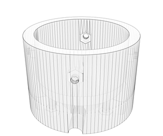
Step 6: Enclosure


Boring grey box
After we checked that everything was working properly we moved on to covering up our central "hub" that houses the PCB and 5W power supply. Because we were planning to route the wiring of the lamps into our office's ceiling anyway, we decided not to go for an aesthetic solution here.
We bought ourselves a nice little Fibox project enclosure that is rated IP65 (meaning hardcore resistance to dust and water) and a few cable glands to allow our wires to protrude from it. We drilled some holes for the glands and screwed them in, and that was basically it. No unessecary effort put into this part of the design. the PCB is mounted on adhesive posts and the powersupply was stuck in with a piece of double sided tape. Then we screwed on the lid and chucked it into our tile ceiling.
I included a little illustration of the box contents (done with my best MSpaint skills) to illustrate the connections between components in the enclosures and where the cables enter and exit.
Step 7: Wire and Mount!


All that was left now for the hardware was the final cabling and hanging of the lamps! To make sure we mounted them correctly we mocked up our meetingroom in our 3D software (Fusion), and tried out some different angles and configurations before drilling holes in the ceiling.
After a poll on Slack and some discussions we chose our favorite orientation and measured out the hole distances on the ceiling. Some quick drilling, pulling of cables and tying knots later we had everything up and running!
After putting back all the ceiling tiles in their respective places, this was a nice moment to step back and marvel at what we had created. But we weren't there yet! We still needed to get some programming magic done to get everything working. Luckily we could do this all from the comfort of our desk behind our laptops and beam all the code to our Photon over the air!
Step 8: Coding

We haven't done a lot of experimenting with the code as of yet. But i'll explain a simple way to make these lights work over the internet using simple Particle functions and IFTTT.
The Particle IDE is super easy to use for anyone that has programmed an Arduino type device before. You can find it at build.particle.com. Once logged in, a text editor appears, here we write our code.
The code we use follows a few simple steps:
1. Declaration of variables
In the first part of the code we have to initialize the libraries and variables we want to use. The Neopixel library is needed to light up the neopixels, the particle library is added automatically and includes the particle cloud functions we will be calling. We also have to set the system mode to automatic, which means the photon won't run code unless there is a connection to the cloud. You have to set up the photon to connect to your WiFi via the app or command line interface first ofcourse.
// This #include statement was automatically added by the Particle IDE.
#include "Particle.h"
#include "neopixel.h"
SYSTEM_MODE(AUTOMATIC);
Then we set the variables for the NeoPixels to use including digital pin numbers, LED type and brightness of the strips. Also the different strips are defined from strip one to strip four. The strips all share the same pixel count and pixel type properties, as all the strips are identical:
#define PIXEL_PIN1 D0
#define PIXEL_PIN2 D1
#define PIXEL_PIN3 D2
#define PIXEL_PIN4 D5
#define PIXEL_COUNT 19
#define PIXEL_TYPE SK6812RGBW
#define BRIGHTNESS 255 // 0 - 255
Adafruit_NeoPixel strip1(PIXEL_COUNT, PIXEL_PIN1, PIXEL_TYPE);
Adafruit_NeoPixel strip2(PIXEL_COUNT, PIXEL_PIN2, PIXEL_TYPE);
Adafruit_NeoPixel strip3(PIXEL_COUNT, PIXEL_PIN3, PIXEL_TYPE);
Adafruit_NeoPixel strip4(PIXEL_COUNT, PIXEL_PIN4, PIXEL_TYPE);
2. Setup
In the setup we have to set up our particle cloud functions, these are the functions that allow us to communicate with the Photon via the particle cloud. You give the function a name, in this case we called it "Sign", and define a string that can be filled with commands of max. 64 characters, we called this "signToggle".
After this we start up the NeoPixels, these are set to an initial black or "off" state and full brightness
void setup() {
//particle functions Particle.function("Sign", signToggle);
//Initialize Neopixels
strip1.setBrightness(255);
strip2.setBrightness(255);
strip3.setBrightness(255);
strip4.setBrightness(255);
strip1.begin();
strip2.begin();
strip3.begin();
strip4.begin();
strip1.show();
strip2.show();
strip3.show();
strip4.show(); }
3. Loop
In the loop we call the function that describes the neutral state of the lamp (Full white LEDs blasting). Thats really all we do in the loop. When we call our particle function the loop will be broken and the contents of the "Sign" particle.function will be executed. The fullWhite function we point to will be described after the main loop in the functions section.
void loop() {fullWhite();}This section continues in next step!
Step 9: Coding Continued
4. Functions
Now we fill up our functions with what we want them to do. The fullWhite function tells each individual Pixel in each strip to become white. We then let the code listen to the strings that are received in signToggle and whenever this string is "go" we turn all the LEDs red and hold this for 2000ms. After doing this the pixels will turn back to the neutral white state. (Full code is attached as .bin)
void fullWhite() {
    for(uint16_t i=0; i<strip1.numPixels(); i++) {
    strip1.setPixelColor(i, strip1.Color(0,0,0, 255 ) );
    strip2.setPixelColor(i, strip2.Color(0,0,0, 255 ) );
    strip3.setPixelColor(i, strip3.Color(0,0,0, 255 ) );
    strip4.setPixelColor(i, strip4.Color(0,0,0, 255 ) );}
    strip1.show();
    strip2.show();
    strip3.show();
    strip4.show();}
int signToggle(String command)
{
if(command == "go")
{
for(uint16_t i=0; i<strip1.numPixels(); i++) {
strip1.setPixelColor(i,strip1.Color(255,0,0,0));
strip2.setPixelColor(i,strip2.Color(255,0,0,0));
strip3.setPixelColor(i,strip3.Color(255,0,0,0));
strip4.setPixelColor(i,strip4.Color(255,0,0,0));
strip1.show();
strip2.show();
strip3.show();
strip4.show();
delay(2000);}}}Attachments
Step 10: IFTTT


So now we have hardware, and firmware! All thats left to do is set up a trigger for our particle function. As said, we can use IFTTT to create easy triggers for the Photon. Ofcourse you can also access an endpoint and integrate this into something more custom, but for the sake of simplicity we will use this great webservice that does all the API integration for you.
First of all connect your google agenda and particle accounts. You can do this via the "services" page. Search for "google agenda" and "particle" respectively and create the link to IFTTT by logging in to these services.
Now create a new applet via the "my applets page". You will be presented with a huge "if this then that" text. Click on this. Now find your google agenda service and tell the applet to trigger when new events start. Then press that and find your particle service. In the window you are presented with you will see that the particle.function ("Sign") shows up in the first dropdrown. Select this. Then define the function input to send when a new event is sbout to start. remember, we use the string "go" to trigger a red flash... so enter "go" in the function input field (without parentheses).
Thats it! You now should have a working light installation that listens to your google agenda and alerts you with a red flash whenever a meeting is about to start.
Step 11: In Action!

So thats it! All the steps we took to make our meeting room more interactive. We're still working at hard at developing fitting interactions and extra integrations for the lamps, and ofcourse we're very interested in suggestions and tips for further development. Again, if youre interested in smart buildings take a look at our website! Also, youre very welcome to post any questions you have below, and i will try to answer them!
Hope we inspired you, and we cant wait to see what the community thinks of the project!
Yours truly,
The Mapiq team


