

Introduction: Nixie Tube Music Visualizer


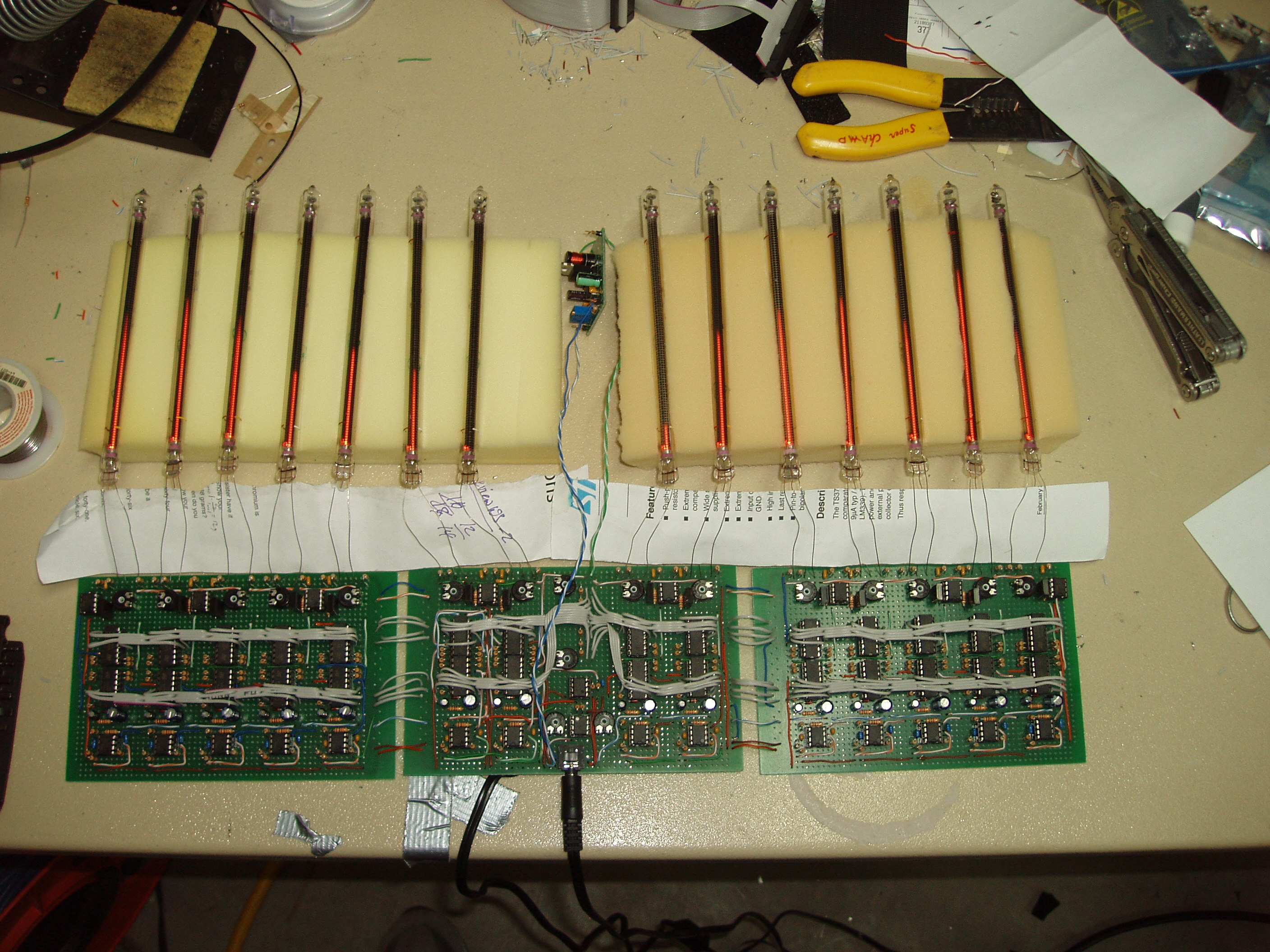
The length that each nixie tube lights up represents the volume of a certain frequency in the music, 7 different bands for both the left and right channels.
I designed and built this over a month my junior year in high school. This instructable will go over my design process and the construction, hopefully aiding anyone who wants to build one of their own.
Step 1: Design Process


- Minimizing cost: In the process of designing the visualizer, I found this simple VU meter with a nixie display utilizing an exotic IC to convert an audio signal into a volume level. While convenient, it's manufactured by a small company, and each piece would cost over $5 (for me, nearly $80 in those alone!) For simplicity and for my wallet, this only uses simple, cheap, and mass-produced parts. Also because of cost, I decided that 10K ohm resistors would be used for just about everything, so I could buy a few hundred for around $3.
- Analog only: Using a digital signal processor was a possibility, but programming a DSP is fairly difficult, and the cost of DACs for the input and ADCs to drive the output began to raise the price too far. So only analog parts such as op-amps and comparators would be used.
- Adjustability: After Nixie IN-13 tubes were chosen as the display, I realized that the only documentation was in Russian (or poorly translated English) and not very informative. Not knowing anything at all about how much it took to light it up any specific length (aside from less than 4 milliamps ), everything about this design would be adjustable.
Step 2: Design: Amplification

A standard dual op-amp (I used an LM358N from National Semiconductor) does the job nicely, amplifying both channels independently. Two potentiometers make each channel's gain adjustable.
Step 3: Design: Filter


Each audio channel splits out into 7 different bandpass filters. The filters are centered on 60Hz, 150Hz, 400Hz, 1kHz, 2.5kHz, 6kHz, and 15kHz. Each filter is a Fliege band-pass filter, which has a relatively low count of components, and works well from a single supply (0V and 12V, as opposed to +/-6V). Each Fliege filter uses two op-amps, so another cheap dual op-amp can be used.
The following chart gives the values of the resistors and capacitors for each bandwidth (R4 and R5 are both 10kohms). If you are calculating your own bandwidths, I used a Q value of approximately 5 (none of them are exactly 5 because of the limitations of standard resistor and capacitor values).
Step 4: Design: AC to DC

Now that there are seven different audio signals for both channels, each containing a different frequency band, they are all converted to a DC volume signal. A 100uF polarized capacitor removes the 6V DC bias on the audio signal. A small signal diode rectifies the signal, discarding all of the negative values. Finally, the signal is smoothed out by a 4.7uF capacitor in parallel with a 10K ohm resistor. A DC voltage of the recent average volume of the signal is the result.
Step 5: Design: Logarithmic to Linear


This is the stage that would be way easier if I could afford the $80 in THAT Corporation's fancy true-RMS and log-calculating chips. The problem is that what we perceive as volume doesn't directly translate to the voltage of an audio signal. When you double the amplitude of a signal, it doesn't sound twice as loud, it sounds Log(2) times louder. Skipping this stage would make the display spend nearly all of the time at the very bottom, and spiking high when the sound gets particularly loud.
One way of solving this is by generating several reference voltages, one at the quietest level that the display should detect, one at +3dB, one at +6dB, and so on. The volume signal can then be compared to each of these references. For every reference voltage the volume signal is greater than, the display lights an additional unit of length.
An array of seven resistors and two potentiometers is arranged as a voltage divider to generate the necessary eight reference voltages. For each band, eight voltage comparators (in the form of two quad-comparator ICs, I used STMicroelectronics TS3704) compare the signal to these references to determine a linear volume level. The eight outputs of the comparators are then averaged with 10K ohm resistors, giving a range of values from 0V to 12V with each step of 1.5V equaling about 2.1dB.
The values of the resistors in the divider from ground to V+ are:
2k potentiometer, 470, 750, 1.1k, 2k, 2.7k, 4.7k, 7.5k, 25k potentiometer
Step 6: Design: Display


A voltage divider cuts the signal down by 1/2 so it's range is between 0V and 6V. A low-pass RC filter smooths out the very sharp changes in the volume signal (when the level of the nixie tube is changed too quickly, the lit segment jumps out to the middle of the tube, rather than lighting from one end).
The nixie tube has 3 pins, an anode, a control cathode, and an auxiliary cathode. The anode is tied to the output of a high voltage power supply at around 125V. The auxiliary cathode is tied to ground through a 220k ohm resistor. As far as I can tell, the auxiliary cathode acts as a sort of pilot light, forcing the tube to begin to glow at one end first, rather than from the middle or the other end. The control cathode is the main tube, and the current through it determines the length of the tube that is lit. A high voltage NPN transistor modulates the current from the control cathode through a 470 ohm resistor and potentiometer (for tuning purposes). The base-emitter junction of the transistor has a forward bias voltage of about 0.65V that it needs to turn on, so an op-amp is used to adjust the signal for this.
Step 7: Design: Power

The majority of the visualizer runs off of a 12V DC power supply. The audio in, amplification and filter stages need 6V power (1/2 the supply). The 6V is created by a voltage divider of two 100K ohm resistors. This setup cannot actually source any real amount of current, so it is connected to to non-inverting input of an op-amp (TL3472), with its output connected to its inverting input. The output of the op-amp centers perfectly at 1/2 the supply voltage, and it can source current.
The display stage needs 125V to power the nixie tubes. Creating high voltages with a boost converter requires a very precise layout of the traces, so I purchased a prebuilt one from allspectrum.com
Step 8: Construction: Parts
15x 470 ohm resistor
1x 780 ohm resistor
14x 1k ohm resistor
1x 1.1k ohm resistor
4x 1.6k ohm resistor
1x 2.0k ohm resistor
9x 2.7k ohm resistor
4x 3.9k ohm resistor
1x 4.7k ohm resistor
4x 6.2k ohm resistor
1x 7.5k ohm resistor
2x 8.2k ohm resistor
170x 10k ohm resistor
8x 11k ohm resistor
4x 15k ohm resistor
2x 20k ohm resistor
2x 33k ohm resistor
4x 56k ohm resistor
2x 100k ohm resistor
14x 220k ohm resistor
2x 250k ohm potentiometer
1x 25k ohm potentiometer
15x 2k ohm potentiometer
14x 100uF electrolytic polarized capacitor
14x 4.7uF electrolytic polarized capacitor
18x 1uF capacitor
13x .1uF capacitor
8x .01uF capacitor
4x 1000pF capacitor
23x LM358N dual op-amp
1x TL3472CP dual op-amp (higher output current)
28x TS3704 quad voltage comparator
14x MJE340 NPN transistor
14x 1N4148 signal diode
24x 8-pin DIP socket
28x 14-pin DIP socket
1x stereo 3.5mm audio jack
14x IN-13 Nixie bargraph tube
3x Prototype PCB, 1-hole island, Eurocard size
1x 12V AC/DC adapter
All of the passive components were bought from Digikey, while the ICs and transistors were bought from Mouser, because they were considerably cheaper. Allspectrum.com sold me the prototype PCBs, the AC/DC adapter, and the high voltage power supply designed for nixie tubes. Sergey Bochkov at tubes-store.com sold me the actual nixie tubes. Even though Tubes-Store is run out of Chelyabinsk, an odd industrial city in Central Russia, and it appears that I was only the 5th person to ever buy from the site, they are cheap and shipping was reasonable.
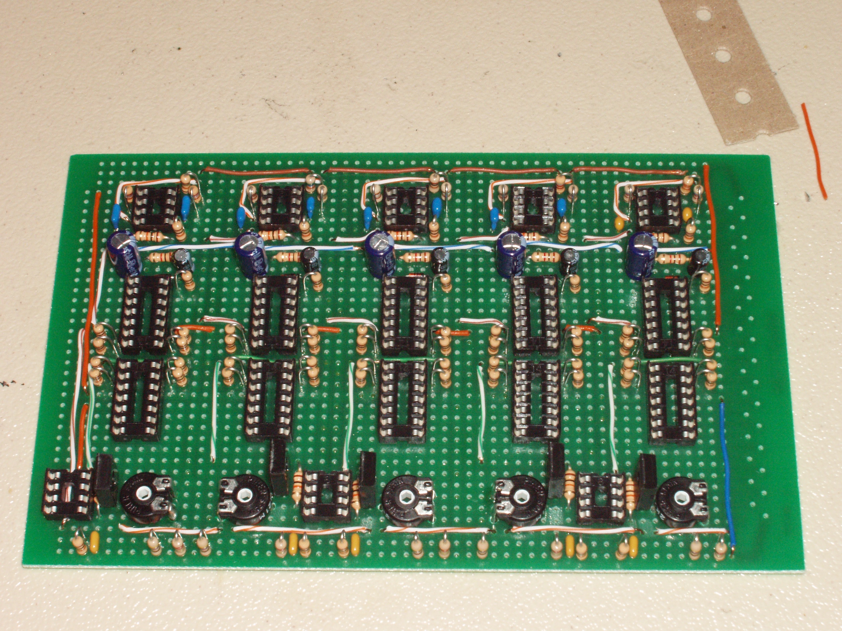
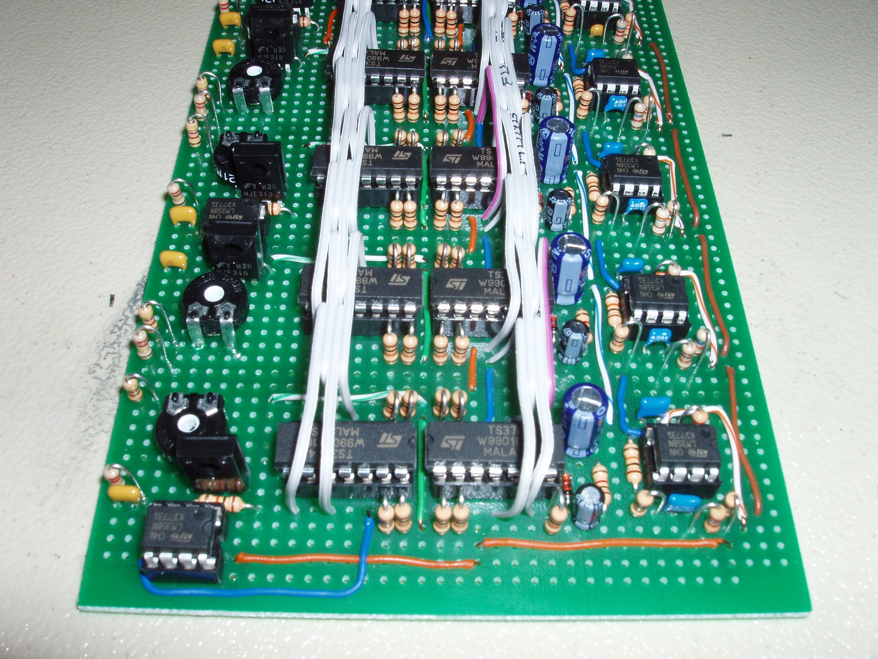
Step 9: Construction: Layout


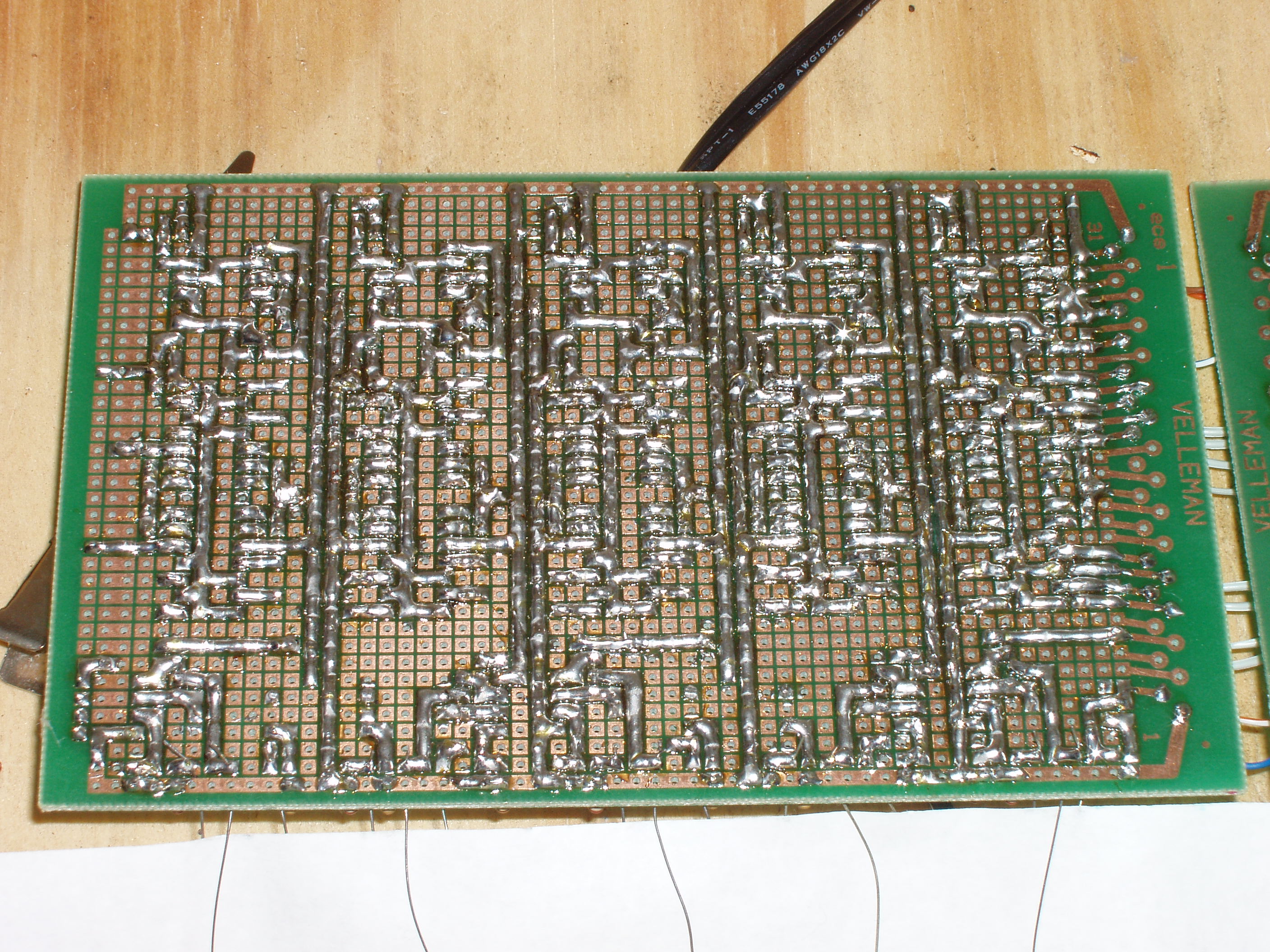
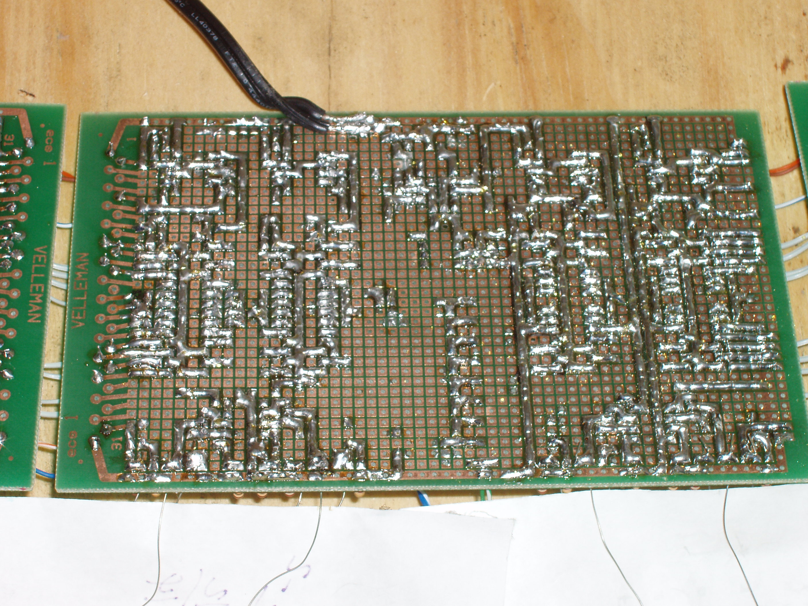
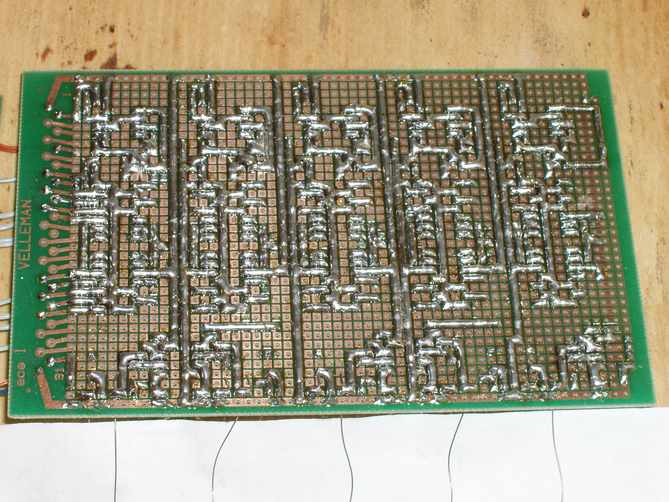
The entirety of the construction is done by soldering adjacent pads on the bottoms of the PCBs, using wire on the top if necessary.
Each board has a long trace along the top and bottom. The top is connected to the 12V power supply, while the bottom is connected to ground.
Every bandwidth occupies a vertical strip of PCB, with, from top to bottom, the filter, AC to DC, Log to Lin, and Display circuits. The nixie tubes are then attached to the bottom of the board, where they can be mounted.
Each band takes up about one-fifth of the space on the board, so the left and right boards each have 5 bands, while the middle board has two bands on the left, two on the right, and circuitry common to both the left and the right channel are shared in the middle fifth of the board.
The middle segment has the audio input jack, the amplification for the left and right channels, the 6V power, and the voltage divider for all of the log-to-lin circuits.
Step 10: More Info
If you want to build your own, I hope I included enough information to allow you to make it your own, customizing any part of it, changing the number of tubes, channels, or anything. Here are links to high resolution pictures and the eagle files I used for construction.
Visualizer
Left Board Reverse
Middle Board Reverse
Right Board Reverse
Part Layout
Side View
EagleCAD schematic and board files
If you have any questions, feel free to shoot me an email at admin -at- tchips -dot- com
First Prize in the
Art of Sound Contest


