

Introduction: Nunchuk-controlled Helicopter


Today we're going to build a 'device' to control a mini-sized helicopter with a Wii Nunchuk.
The helicopter that we're using is a cheap (26$) 3-channel (yaw, throttle, pitch) helicopter that I bought a 1 month back from Dealextreme.com . I can say that it is a VERY durable heli : I have crashed more thant 100 times and it's still working ! It is not radio-controlled, but rather Infrared-controlled, so easier to reverse-engineer. I should also say that in this instructable, the original remote won't be harmed, everything can be done without opening it or even opening the helicopter itself. That means we have nothing to lose :D
In this instructable we're going to take a look at reverse-engineering the Infrared communication with a IR demodulator (very cheap), we'll also learn to use our beloved Arduino as a 1Mhz 'full-featured' logic analyzer. Finally, at the end, there's loads of fun flying the heli around with a nunchuk !
But be warned : as I'm away from home, I won't be able to provide you with a clean PCB to arrange all the components, this is more a quick-and-dirty hack than a real (and finished) project.
Please rate this Instructable ! And also, if you're actually building the thing (or have problems building it), please post a quick comment, I'm always happy to learn I've helped people out !
If you're in, let's go : step 1, the required stuff
Step 1: Required Stuff

Required tools:
- soldering iron
- solder wire
Required parts:
- Arduino (I use a Mega, but any Arduino will be just fine)
- Mini-Helicopter (This project can easely be ported to work on a Syma S107, and any other heli if you reverse-engineer the IR pulse yourself)
- Wii Nunchuk
- 9v battery with 9v battery clip an jack
- TIP120 transistor
- 38kHz IR detector/demodulator
- 10kOhm potentiometer
- 10 ohm resistor
- 4x AA batteries
- 4x AA battery holder (optional, used if you don't want to break your original remote)
- 3x IR leds (used if you don't want to break your original remote)
Required software (for now) :
- Arduino IDE, get it here
- SUMP OpenLogicSniffer client (special version), get it here .
Ok, I think everything's here, so let's head to step 2...
Step 2: Infrared Modulation

Now, this is the theory, if you don't want to know how to reverse-engineer an IR remote control, you can just skip to step 6.
Ok, so the helicopter isn't controlled with a 'normal' radio remote, but is controlled with a cheaper Infrared remote.
This is just great because we can more easely reverse-engineer the thing ! We only need a component called an IR detector or IR demodulator.
Now this page has an excellent tutorial on how infrared modulation works, but I'm only going to resume it quickly here :
As you know, the sun, as well as most heat sources, including light bulbs, emits infrared radiation. Infrared modulation is a technique that involves PWM-ing an Infrared led at a certain frequency (here 38kHz) to 'bypass' the IR radiation from ambient light : the IR demodulator only accepts 38kHz modulation, filters out everything else, and gives a clean logic (0 or 1) output. It gives a logic LOW (0volts) output when it detects a modulated IR signal.
There's a device like this on all TVs/DVRs/DVD players, etc.. Fortunately, this thing doesn't cost much , is really easy to interface with a microcontroller/logic analyzer and will allow us to reverse-engineer the IR protocol used by our helicopter remote without opening the remote !
BTW, the image below kinda illustrates well how IR modulation works : the remote gives the signal on the left, the demodulator gives the one on the right.
Now let's move on to step three : preparing our improvised 'logic analyzer' .
Step 3: Preparing the Logic Analyzer


So now, you know how the transmission physically works, and what the demodulator will output. It outputs logic HIGH (5v) when no signal is detected, and logic LOW (0v) when a modulated signal is detected. All right, enough theory. How are we going to record and use this signal ? We need a logic analyzer. Unfortunately, these types of tools don't come cheap (~150$ for the Logic ), but the Arduino community really has a lot to give, and someone named gillham made an Arduino sketch that transforms the Arduino into a SUMP-compatible 1MHz logic analyzer. Yeah, 1MHz isn't brilliant, but hey, it's free, and it will suffice for our light use.
- You have normally already downloaded the modified SUMP client in Step 1. If not, here it is.
- You'll also need the logic_analyzer.pde Arduino sketch
- Connect the IR demodulator's data pin (the one on the left) to the Arduino's pin 8.
- Connect the demodulator's GND (middle pin) to the Arduino's GND
- Connect the demodulator's Vcc (Right pin) to the Arduino's 5v supply.
- Extract the OLS zip, connect your arduino via usb, and execute the run.bat (if you're under windows) or run.sh (if you're on linux).
- Now hit the 'Begin capture' button, select the serial port your arduino is using, choose 115200bps speed
- In the 'device type', choose the "Arduino Generic Logic Analyzer" profile.
- In the 'Acquisition' tab, choose 20kHz sampling rate, check the 'automatic recording size' checkbox.
- In the 'Triggers' tab, enable the triggers, and in all the checkboxes on the bottom, check the top-right one.
- Now click the 'Capture' button and raise the throttle on the heli's remote.
- If you have any problems, post a comment, I'll help you. ;)
Note: You can get a sort of 'manual' on the OLS here , and also, I apologize for the poor image quality, but this is caused because Instructables.com compresses uploaded images. :(
Ok, so everything is ready, let's dive in ! Step 4: Capturing IR pulses...
Step 4: Capturing IR Packets


All right, so now that your 'logic analyzer' is ready to go, we're going to start the actual reverse-engineering : 'intercept' the IR signal that goes from the remote to the helicopter. In the next step, I'll attempt to decode this signal, and create one from the Arduino.
So just click on the capture button, and crank up the throttle on your remote. Zoom in a little bit, and you'll see a signal like in picture 1. The signal is read from right to left
- As you see there are times when the 'ON' period is long, and times where it's short. At the beginning, there's a very long 'ON' period, we'll deal with that later.
- Right-click on one falling edge of the short 'ON' signal, select set cursor 1 (for better precision, use the zoom)
- Right click on the corresponding rising edge, select set cursor 2 (see pic2)
- Now go to Tools-->Measure, check the 'Distance' value, and write it down : write short_ON=[distancevalue] in a txt file.
- Do the same thing for the 'OFF' (check pic3), and write down : OFF=[distancevalue]
- Do the same thing for the long 'ON' period, and write down : long_ON=[distancevalue] (see pic4)
- The very long 'ON' period at the beginning of the signal is called a header. Measure it, and write down : head_ON=[distancevalue]
But now, how will we decode the binary stream (0s and 1s) sent by the remote? One would think that a 'ON' period is a 1 and an 'OFF' period is a 0. But then, why are there longer 'ON' periods, and why are all the 'OFF' periods the same size? The reason is that :
- a 1 is a long 'ON' period followed by an 'OFF' period (see pic4)
- a 0 is a short 'ON' period followed by an 'OFF' period
Now that we have figured out how to 'translate' this IR signal into a series of 1s and 0s, we still need to know which 0s and 1s control which part of the heli (the yaw, pitch, etc...). For this, we will try to write down that series of 1s and 0s in every possible configuration of the remote, (e.g. Full throttle-yaw centered, then Full throttle-yaw to the right, then Full throttle-yaw to the left, etc...). Then we can figure out which combination of 1s and 0s corresponds to which part of the heli, by seeing which 0s and 1s change in which remote configuration. Now, to better see the changes of the 1s and 0s, we can color them differently using a intelligent notepad. I made it under notepad++ in windows (you can use it with wine on linux). At the end, I got a text file looking like picture 6. Then I tried to decode it and made another text file describing which helicopter components were affected to which bits : here it is.
With this info, you should be capable of reverse-engineering the IR protocol of any similar helicopter. If you do, please post a comment so I can integrate it in this instructable.
Next step is recreating this IR pulse in Arduino. Ready, let's go !
Step 5: The Arduino Sketch

So, um, well, I'm not really going to explain how the code works here, but, all I can say is that to generate the IR pulses, I got the code from this blog, that I heavily modified to work with my heli, and then I got the nunchuk handling part from Tod E. Kurt (todbot.com) and used it to control the heli.
To send an IR packet, you call this function :
SendCommand(throttle, yaw, pitch, trim);
with,
- throttle 0-255
- yaw 0-255
- pitch : 1=backwards, 2=forward, 0=none
- trim 0-255
So don't forget to read the description at the beginning of the code, an that's pretty much it !
Oh, I almost forgot ! You can get the code here ^^
Now, let's head to step 6 : the hardware setup.
Step 6: The Hardware Setup

Okay, now that we're done on the software side, we will focus on building the hardware that goes with it. As I said in the Introduction, I'm currently away from home (and for a long time), and I don't have access to my laserprinter, that means that you won't get a clean pcb this time :'( Indeed, the hardware setup here is kinda messy.
- Due to the low discharge rate of 9v batteries, I prefer using a separate power supply for the leds, to avoid any brown-outs on the arduino. Here, I just used the old remote's case because of it's battery holder. If you want a cleaner layout, just buy a battery holder . I use 4 AA batteries to power the leds.
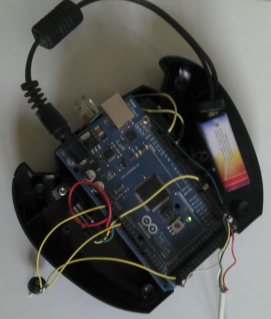
Now for the wiring (take a deep breath) :
- chop off the nunchuk's connector (or use this)
- connect the nunchuk's red wire (Vcc) to the arduino's 5v supply
- connect the nunchuk's white wire (gnd) to the arduino's GND
- connect the nunchuk's green wire (SDA) to the arduino's Analog pin 4
- connect the nunchuk's yellow wire (SCL) to the arduino's analog pin 5
- connect the 3 IR leds in series, with the 10 Ohm resistor to the external supply's +
- connect the IR leds cathode with the TIP120's collector (middle pin)
- connect the TIP120's emitter (right pin) to the arduino's GND
- connect the Arduino's GND to the external supply's -
- connect the TIP120's base (left pin) to arduino digital pin 2
- connect the potentiometer's left wire to the arduino's 5v supply
- connect the pot's right wire to the arduino's GND
- connect the pot's middle wire to arduino analog pin 0
- connect the 9v battery to its clip and plug it in the arduino's power jack.
- check the picture for any errors.
Now program your Arduino, and head to step 7 to begin having fun (finally !)
Step 7: Controlling the Helicopter

Enough work ! No, really, YOU need a break ;) In this step, I'll explain how to control your Helicopter with your freshly-wired system.
- The nunchuk's C button (the little round one) is the Dead Man's switch. Always have it pushed down. If you release it, the Helicopter will receive the Stop command and will stop moving it's blades.
- You control the throttle (up/down) by tilting the nunchuk forward and backwards
- The joystick's X axis controls the Yaw (left/right)
- The joystick's Y axis controls the pitch (forward/backwards)
So this instructable is coming to an end, but stay tuned, because I'm currently building another remote for the heli, but this time, I'll be using an Android smartphone as the remote (It will be ready in 1 or 2 months)
- All right, so now, Have Fun ! (and spread the word ^^)


