

Introduction: Observercade


CLASSIFIED - TOP SECRET
FRINGE DIVISION - Department of Homeland Security
EVIDENCE REPORT
CASE NO: 32A-UG-82263P
Evidence Description: Black Samsonite briefcase with internal electronics
Location Evidence Found: Belle Motel, room 243, Lowell, MA
Date/Time of Recovery: November 19, 2009, 21:00 EST
Suspect: Observer 2 aka "August"
Offense: Abduction
Victim: Christine Hollis
Evidence Recovered by: Colonel Phillip Broyles of Fringe Division
Report by: Astrid Farnsworth - FBI Junior Agent - Boston Office
Evidence Retrieval Process: Following the rescue of the victim, a thorough search of room 243 and surrounding area, was performed by the crime scene team, led by Agent Broyles. One of the articles found was a black briefcase. The briefcase was closed but unlocked. It was found laying flat on a small dining table in the motel room. The item was bagged/tagged and delivered to the Fringe lab in Boston for further analysis.
Step 1: Evidence Analysis


Overall Dimensions: 18 inches x 13 inches x 3.75 inches
Weight: 12 lbs
General Description: The briefcase contains a monitor that is housed in the top half. The bottom half has a storage compartment which holds a power cord and a detachable joystick. The bottom half also holds the joystick mechanism and eight push button switches. There are 3 blue, 3 green and 1 red push buttons. There is an illuminated rocker type switch on the right edge.
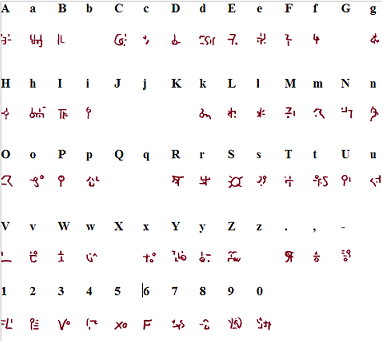
The push buttons are labeled with Observer symbols which were deciphered using Agent Astrid Farnsworth translating software. http://24.media.tumblr.com/tumblr_matdvzeXA31rrm8m... Roughly translated and extrapolated from usage of the device, from left to right the labels are as follows: "Credit", "Player", "Pause", "Escape", "Shoot", "Jump", "unknown." For "testing" purposes, the buttons were labeled in English with blue masking tape.
The monitor has three unmarked tiny black buttons on the left side, vertical surface. Determined from usage, the bottom button is the monitor power button. The top two buttons adjust the volume.
Construction: The unit was disassembled and examined in finer detail. The disassembly was rather straight forward. Phillip head machine screws where used in most of the construction. The horizontal control surface was made of 1/8 inch sheet acrylonitrile butadiene styrene (ABS). It was secured to the the bottom portion of the briefcase via various strips of aluminum angle and machine screws. The bottom portion also housed a "brick" style power supply located in the upper right corner.
The backside of the horizontal control surface holds all the electronic circuit boards. The boards are mounted via plastic stand-offs. The mounts were manufactured via 3D FDM printing.
The top half of the briefcase holds the monitor. The screen bezel is 1/16" sheet polystyrene. The 17 inch liquid crystal display (LCD) was salvaged from an HP laptop computer. The laptop's external housing was used to mount the LCD to the top half of the briefcase. Additional mounting infrastructure consists of 1/2" foamed PVC formed to hook on the lip of the briefcase. Two small circuit boards were fixed to the laptop housing. One board, located on the left, controls the LCD functions. The other board, located on the bottom, drives the LCD back light.
Parts:
Raspberry Pi Model B
Mausberry Shutdown Circuit
Power Adapter, Model 1205, Rated 120-240, 1.5A, 50/60Hz, Output 12Vdc, 5A eBay
2 - 40mm dia. Speakers
e-qstore LCD Driver Board kit on eBay
Adafruit UBEC DC/DC Step-Down (Buck) Converter - 5V @ 3A output
7 - Adafruit 30 mm Arcade Buttons
Sanwa Joystick
Focus Attack The Link, quick release joystick shaft
Illuminated Power Switch rocker style from auto parts store
Zero Delay USB Arcade Encoder Board eBay
Conclusion: The device is a simple vintage arcade game emulator. Experts in the field call this a Multiple Arcade Machine Emulator (MAME). It is a simple computer that runs video games found in video arcades located in shopping malls during the late 1970s.
It is unknown why the Observer hand-built this device. The device appears to have little use other than simple amusement. Like his love for the victim, it is speculated that the suspect's human emotions were getting the best of him.
Next, I will attempt to make the perfect strawberry milk shake.
Analysis Performed by: Dr. Walter Bishop
Step 2: What Did I Just Read?

Fans of the TV Show Fringe may have gotten the subtle humor behind the fake evidence report outlined in the previous steps. I was taking some artistic license with this Instructable. : p
For those not familiar with the show, there were characters from the future called the Observers. They were all bald and lacked eye brows. Each of them were dressed in a gray suit and wore a stingy brim hat. And here's how this Instructable is connected to Fringe, some Observers carried a black Samsonite briefcase circa 1970s to early 1980s. I actually owned one of these briefcases.
A few years ago, a posting on HACKADAY inspired me to utilize my briefcase in a project. The posting covered a build by Travis Reynolds. It was a MAME inside a briefcase. That build was called The Briefcade. http://hackaday.com/2014/01/03/arcade-briefcase-th... So, this Instructable is about a Fringe themed Briefcade! : )
I am rating this project as expert level or high difficulty because there were many fails. For example, I had to do the monitor braces three times and the storage compartment twice. The frustration level was so high I ended up buying a 3D printer half way through the build.
Step 3: Prep the Briefcase


The first thing I did was to yank the internal folder dividers from inside the lid of the briefcase. This is fairly easy since the dividers are sewn on. I used an exacto-type knife and carefully cut the threads.
Next, I noticed that the briefcase wasn't an ergonomic match for playing video games. The lid was angled too far forward and the case rocked slightly on a flat surface. The rocking was easily corrected by adding some rubber feet to all four corners. The feet measured 3/4" in dia. by 1/2" tall. They're mounted with machine screws and nuts.
The angle of the lid was a bit more complex. I ended up adding an extension "link" to the both hinges. That did two things: it laid the lid back further for a better viewing angle and also provided a way to lock the hinges. It would be a bad thing if the lid was accidentally closed while the joystick was still in place.
The extension link was fabricated from 12 ga. sheet metal. The link measures 1" x 1/2" Two 1/6" holes were drilled 3/8" apart. Two slots were cut with a hacksaw and twisted to form a rotation "stop" which is needed so that the hinges can't rotate in the wrong direction. To install the links just drill out the existing hinge rivets and pop rivet in the new links.
For my briefcase I had to repair some damage. I ran over it with my car so the lower right corner had a tear in it. I repaired this with a fiberglass repair kit that I bought at an auto parts store. Some sanding and painting restored it to almost like new.
Next was mounting the power supply. I wanted to easily remove the power supply so I blocked it in place with some 1/2" foamed PVC (Sintra) sheet. I positioned the power supply where I wanted it and used cardboard to mock up some templates. The templates were transferred to the foamed PVC. The foamed PVC was cut then epoxied into the briefcase. I didn't want the power supply to move around so I fabricated a holding bracket using scrap metal (old hard disc dive cover) that I bent 90 deg, That bracket was screwed into the foamed PVC. Lastly, I cut a hole in the back corner of the briefcase that lined up with the power connector inlet.
Step 4: Install the Monitor


This step was a bit frustrating but first some background. The monitor was pulled from an old laptop. My bother-in-law had a 17" HP laptop with a bad motherboard, which he gave to me for free. I disassembled the laptop and found that the LCD mounts to the top lid, the part with the HP logo. I decided it would be easier to mount this lid to the briefcase rather than mounting the LCD directly to the briefcase. This would allow me looser tolerances.
Cannibalizing a monitor from a laptop requires use of an "off-the-shelf" video controller board. Find the manufacturer and model number of the LCD then search for it on eBay. I found one from a vendor called e-qstore. They have great customer service. The kit contained a HDMI input, audio amplifier and all the boards and cables needed for plug and play. The kit I bought had a signal cable that was too short. I contacted e-qustore and bought a longer one. All the transactions went smoothly. Another cable that was too short was the button board cable. I extended this via a ribbon cable.
First, I fabricated the monitor braces. There are six braces in total, two horizontal and four vertical. The braces are made of 1/2" foamed PVC (Sintra). I positioned the LCD lid and created some cardboard templates. I transferred the templates to the foamed PVC and cut them out with a jig saw. Then after many fittings and sanding, I attached the two vertical pieces to the horizontal piece by epoxy and screws. (Note, the photos shows MDF braces rather than the white foamed PVC. The MDF was a big fail.)
Next, I needed to mount the two circuit boards. One was the back light driver board, the other is the button board. The button board controls the monitor settings and volume. The power on, volume up and down buttons were replaced with buttons that had longer stems. I also flipped the header connector to the opposite side of the button board. The board mounts were fashioned from sheet plastic and wood. They were epoxied to the back of the LCD lid.
Lastly, the monitor face plate. This was made from 1/16" sheet polystyrene and 1/8" square rods. A large template was made from cardboard and transferred to the sheet polystyrene. The 1/8" square rods were used for edging and attached with common model glue. The edging was formed around the semi-circles with a heat gun. I carefully measured and drilled holes for the button board on the left side. The face plate is attached to the foamed PVC braces with screws.
Step 5: Fabricate the Control Panel


Here's the meaty part, the control panel that holds the joystick, buttons and compartment.
First, I created a big template for the bottom half of the briefcase. I transferred and cut the template from a sheet of 1/8" ABS. Next I placed all the components to find all the best position for everything. The remaining space dictated the size of the storage compartment.
I designed the storage compartment box to hold the joy stick and power cord. Using those dimensions, I fabricated a five sided box. The height of the box was determined by both the diameter of the joy stick ball and the depth of the bottom of the briefcase. The bottom of the briefcase has some flex or give so I wanted to allow for this in the design.
The storage box was built using ABS solvent which is just acetone. Acetone was used to attach the box to the control panel. I added in corner magnets to hold the lid closed. The lid was made by the same sheet polystyrene used on the monitor face plate. Triangular metal pieced were glued to the inside of the lid that matched the location of the magnets. A second layer of polystyrene and 1/8" edging was added on top to give the lid rigidity. A finger hole was drilled and shaped as a joy stick. Lastly, I designed a hinge in Autodesk 123D and 3D printed them in ABS and glued them in place.
I also designed and 3D printed: speaker covers, speaker mounting base, button edging and mounting bases for all the circuit boards. Joy stick and button holes were drilled and all the 3D mounting bases were glued to the control board.
I used 9/16" aluminum angle around the perimeter of the bottom of the briefcase to attach the control panel. Machine screws attached everything together. The rear aluminum angle had to be doubled in the rear to compensate for the added stresses caused by the monitor cable harness. The latch area around the front corners of the briefcase had to be trimmed with a Dremel tool so that the control panel could lay flat. Because this latch area became exposed I fabricated a width long L shaped cover from the polystyrene sheet. This covered was attached to 3D printed blocks with captured nuts. These blocks were glued to the control board.
All the electronics were wired up. I used spade connectors on the buttons and JST type connectors for the USB arcade controller board. The power supply output was split to feed the LCD driver board and the Adafruit 12V to 5V DC/DC power converter board. The Mausberry circuit board was connected to the Raspberry Pi with an Adafruit micro usb female breakout board and male connector. The Raspberry Pi was connected to the to the LCD driver board via short HDMI cable. The speakers were connected to the audio out of the LCD driver board. The USB arcade controller board was connected to the joy stick, buttons and Raspberry Pi. The power switch was connected to the Mausberry board and was also powered by the output of the Adafruit DC/DC converter (this powers the red LED in the switch). I fabricated a perf board for this break-out circuit and glued it just above the power switch. The LCD driver board was then connected to the three wiring harnesses coming from the monitor.
Step 6: Paint and Artwork


I prepared all the parts for painting by first lightly sanding the surfaces. Then I painted a base coat of flat black then masked off the parts I wanted to remain black. I then painted the rest in gray hammer tone.
Next I created all the Fringe based art work. I pulled the alphabet references from online. Then I used vinyl ink jet printer paper to create all the decals.
To create another level of realism, I created a Fringe evidence tag and printed it on matte photo paper.
Step 7: Configure the Raspberry Pi


There are a couple of ways to load MAME on a Raspberry Pi. There are many Instructables on how to do this so I won't go into the details. I ended up using RetroPie: http://blog.petrockblock.com/retropie/ on a 16g SD flash card.
I made a couple of tweaks. First I only wanted MAME. RetroPie comes with many emulators as a default. To "remove" all of the other emulators such as Apple and Atari, just delete all the folders and files in those ROM folders. RetroPie will see that there are no programs in those folders and will not display those emulators on the menu screen (emulation station.)
I also wanted a custom Fringe splashscreen displayed during boot up. I modified a Fringe image I found online. Instructions on how to insert a custom splash screen go to this link: http://blog.petrockblock.com/forums/topic/changing... The petRockBlog is a great forum for RetroPie.
Well, that's about it for the Observercade build. Thanks for reading. Please leave comments if you have questions! : )


