

Introduction: Ocean Data Buoy [2.0]
![Ocean Data Buoy [2.0]](https://content.instructables.com/F2J/3MH6/IW6PEO1M/F2J3MH6IW6PEO1M.jpg?auto=webp&fit=bounds&frame=1&height=1024&width=1024auto=webp&frame=1&height=300)


Scientists have been deploying battery powered sensors on ocean buoys for the past 30 years to track currents, waves, temperature, salinity, pH, and other metrics in an effort to understand the ocean. The accepted design standards for these single use instruments typically rely on plastics, urethane foams and lead acid batteries - things that are generally understood to be bad for the ocean. Unfortunately, most of these instruments have a fixed lifespan, becoming ocean trash once they run out of battery power.
I had some success with making my own version of a data buoy (see next step), but this experience left me wondering if it is possible to make a functional data buoy without plastic and batteries. My specific goal is to create seaworthy objects with waterproof electronics enclosures out of materials that will have minimal impact on the ocean if / when they become lost at sea. I spent three months at Autodesk's Pier 9 exploring this question, and what follows chronicles a few points along the way.
Step 1: Previous Research


Thanks to the Arduino and Maker movements, the technology used in data buoys has become more accessible. Over the past year, I developed and deployed my first set of data buoys using Arduino compatible components and code, as well as solar panels and LiPoly batteries. One of my drifters lasted for 6 months in the Pacific Ocean. It transmitted its location as well as the sky color and 30 seconds of wave height info every six hours. I considered this to be a modest success, but I too used a mix of urethane resins, foams and sealants to fabricate a seaworthy enclosure.
Attachments

Step 2: Design in Fusion 360 / Rapid Prototyping


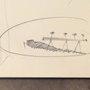
I committed to Fusion 360 as a tool for visualization and prototyping. My end goal was metal and glass, but to get there I needed to be able to see what I was doing in full scale, test, and refine. At the Pier, I was able to do this through 3d printing and laser cutting inexpensive materials. Once a design was developed enough, I could use Fusion 360 to produce more robust prototypes and wood molds for glass blowing with the waterjet and CNC milling.
Step 3: Glass Mold Making


Why glass? I was inspired by the mythic message in the bottle, shards sea glass found on beaches, and the Japanese use of hand blown glass balls in fishing nets. Glass is energy intensive, but the finished material has minimal negative impact if lost at sea. I had the opportunity to experiment with the material thanks to the generosity of fellow Artist in Residence and expert craftsperson, Stefanie Pender.
There is a history of using water soaked wood molds in the glassblowing tradition. Wood is a material I have experience with, and felt like an appropriate way to define the shape of the glass float for the data buoy. Within Fusion 360, I was able to build a virtual mold out of multiple pieces of wood, and subtract the desired shape from each piece. Fusion 360 also enabled me to toolpath my desired shapes and Pier 9 has a wood and foam CNC milling machine made by DMS. I arranged rectangular wood pieces on the DMS table, and used mostly large end mills to remove the unwanted stock and create the voids required for the mold. Once the pieces were cut on the DMS, I had to finish preparing them by hand and assemble them into a glued mold.
Step 4: Glass Blowing


I had no experience with glassblowing prior to this project. Stefanie Pender shared her expertise and provided useful guidance along the way. It was super fun watching her skillfully mold the material. She allowed me to assist along the way. It turns out that successfully rendering a glass shape from a wood mold can be a difficult and iterative process.
The main problem we encountered was getting the mold wet enough to not burn, and porous enough to let the steam escape without changing the shape of the glass. If steam is trapped in the mold, the glass can't fully expand to conform to the hoped for shape. After three different versions of the mold, we were able to produce compelling glass positives from the wood negative. Problem solving along the way involved increasing the amount of steam holes, waiting for the glass to cool, and trying to get the glass as large as possible before it enters the mold.
Step 5: Metal Part Fabrication


The glass vessel's purpose is to provide buoyancy. For proper operation, a data buoy needs to have a set of electronics oriented towards the sky (for communication), and a shape that moves well with the waves. I relied on corrosion resistant aluminum to ballast the buoys. I created full physical prototypes of three different designs, and will test them in the water soon. The main function of the metal parts is to secure the electronics, keep the buoys upright, and dampen wave motion.
I accomplished most of this function with waterjet cut, routed and hand finished metal straps. My 3D Fusion 360 model was put together with 2D sketches. These sketches can be easily exported as dxf files, which can then be cut on the waterjet.
One of the designs was as simple as possible. A second had additional waterjet cut fins for counteracting the pitch and roll of wave motion. The third was the semi-spherical metal cap design. For this piece, I worked with some of the Pier 9 CNC experts to toolpath the Fusion 360 model in FeatureCAM from a solid 12"x12"x2" piece of aluminum stock.
Step 6: Assembly and Testing


I designed the buoys so they could be assembled with simple connections and reinforced with wire wrapping. These connections will probably evolve as I get closer to a seaworthy version, but for now the simple slot connections and metal wrapping provide versatility for testing. Moving forward, I will complete a version of the electronics for recording the buoys movement in the waves during testing, and find a location with appropriate waves to observe their behavior over relatively short periods of time. Once the next phase of testing is complete, I hope to launch a series of finished buoys in the coming months!


