

Introduction: One Pixel Thermometer


Welcome Everyone
Today we are creating a One Pixel thermometer. Quickly see what approximate temperature it is at a glance using a RGB LED (A Pixel)
Step 1: Parts List

We will need the following:
- 1 x Common Anode RGB LED
- 3 x 220 Ohm Resistors
- 1 x 100K resistor
- 1 x NTK100 Thermistor
- Some Jumper Wires
- An Arduino
- And a breadboard
Step 2: The Code

Before we build the circuit let’s have a quick look at the code.
My LED will change from where 0 degrees Celsius is blue and 42 degrees Celsius is red, with green at a comfortable 21 degrees Celsius.
The “defines” in the code allow for some flexibility in the program, I've set my maximum Temperature at 42 degrees Celsius and my minimum temperature at 0. I'll be using the 3 PWM pins 3, 5 and 6 to control the "one pixel".
#define minTemp 0
#define maxTemp 42
#define pinR 4 // Red PWM Pin       use 0 on ATTINY85 (pin 5)
#define pinG 0    // Green PWM Pin     use 1 on ATTINY85 (pin 6)
#define pinB 1    // Blue PWM Pin      use 4 on ATTINY85 (pin 3)
#define pinT A1   // Thermistor Pin    use A1 on ATTINY85 (pin 7)
Declare some global variables that will be used in the Main Loop
// Variables to calculate Centigrade from the Thermistor Pin input value
int Vo; float R1 = 10000, logR2, R2, T, c1 = 1.009249522e-03,
c2 = 2.378405444e-04, c3 = 2.019202697e-07; // <<<---- Magic numbers apparently
In the Setup function I set what each in will do. The three
PWM pins are OUTPUT pins. And the Thermistor pin is INPUT.
void setup() {

// Init Serial

Serial.begin(115200);

// Init Pins

pinMode(pinR, OUTPUT);

pinMode(pinG, OUTPUT);

pinMode(pinB, OUTPUT);

//Don’t really need to do this for the UNO but I'm doing it anyway

pinMode(pinT, INPUT);

}
In the main loop of my program I calculate degrees Celsius from the thermistor value then convert that number to a range from 0 to 512. I then use some a bit of mathematics to get the red, green and blue values for my LED. The LED's colour updates every 100 milliseconds.
void loop() {

// Calculate Centigrade : Got function from <a href="http://www.circuitbasics.com/arduino-thermistor-temperature-sensor-tutorial/">http://www.circuitbasics.com/arduino-thermistor-t...</a>\
Vo = analogRead(pinT);
R2 = R1 * (1023.0 / (float)Vo - 1.0);
logR2 = log(R2);
T = (1.0 / (c1 + c2*logR2 + c3*logR2*logR2*logR2));
T = T - 273.15;
// Map to the range outlined in minTemp and maxTemp
int temp = map(T,minTemp,maxTemp,0,512);
// Assign a RGB value to the range 0 to 512 found in temp
  int r = constrain(temp-256,0,255);
  int g = constrain(256-abs(temp-256),0,255);
  int b = constrain(256-temp,0,255);
// PWM Write to get "faded colours"
// Remove "255 -" if LED's are common Cathode
analogWrite(pinR,255 - r);
analogWrite(pinG,255 - g);
analogWrite(pinB,255 - b);
// Print Temperature to Serial
Serial.println(T);
  delay(100);
}
Upload this sketch to the Arduino, unplug it and start with the circuit.
Attachments

Step 3: Circuit Diagrams


The circuit Diagrams and Breadboard view
Step 4: Building the One Pixel


I'm starting with the RGB LED or the "Pixel"
On most common anode RGB LED's the long pin is the Anode. When looking at the LED with the anode being 2nd pin, the first Pin will be Red; the third is green and the last pin, blue.
- I place the LED onto the bread board
- Connect the three 220Ohm current Limiting resistors from the red, green and blue pins and 3 other terminal strips.
- Connect a lead to the Anode of the LED and 3 leads from the 220 Ohm Resistors
I've used Red, Green, and blue leads to indicate, well, Red Green and Blue
Step 5: Building the Temperature Sensor

Moving onto the Temperature Sensor section
- Put the Thermistor between 2 terminal strips
- Then the 100k Resistor from one end of the thermistor and another terminal strip
- Connect a lead from the unconnected end of the Thermistor and the positive rail
While I'm doing the Positive Leads I'll connect the Anode to the Positive rail too and prepare 2 leads for Positive and Ground to go to the Arduino. I’ve used White for Positive and Black for Ground
- Hook up a lead from the Ground rail to the other end of the 100K resistor
- Then Hook up a lead where the 2 parts meet, I've used yellow to indicate input
Step 6: Connecting the Wires

Now it’s quick and painless to hook all the loose leads to the Arduino
- White goes to 5v
- Black goes to Ground
- Yellow to A0
- Red to 3
- Green to 5 and
- Blue to 6
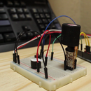
Step 7: Conclusion


Plug in the Arduino
And we have a 1 pixel Thermometer
- I covered the LED with a diffuser I made out of hot glue and a tube of silver paper.
- If I flick a flame over the Thermistor You will see the LED goes Red meaning the temperature is 42 or higher.
- And if I put a cold can on the Thermistor the LED goes Blue
The program will also output the temperatures to serial
Using the serial plotter I can see the flick of flame and the "cool can" when touched against the sensor


