

Introduction: OpenFuge


Specs (Observed):
G-Force: 6000 G's
RPM: 9000 RPM
Size (closed lid): 15cm x 24cm x 20cm
Weight: 1.6 kg
Power Source: Four 18650 Lithium cells
Material Costs: $200
Features:
Adjustable speed and power
Can hold up to 4 Eppendorf tubes
Portable
Safety Interlock
Cleanable
Live RPM monitor and countdown
For DIY people head over to http://www.thingiverse.com/thing:151406/#files and cut out the attached panels. Check out the Bill of Materials (BOM) for the list of parts needed. WARNING: LASER CUTTER REQUIRED (40 min)
For non-DIY people head over to https://www.tindie.com/products/CopabX/openfuge/ and purchase a kit. It comes with all electronics pre-soldered and pre-programmed.
Step 1:
Step 2: Creating the Frame


Laser cut the files from Thingiverse. Make sure you have the smooth side of the wood facing the right direction.
If you do not have a laser cutter, you can print out the .dxf templates on paper. Tape the templates onto the material specified for the pattern, then cut the pattern on a scroll saw.
An optional step before assembling the frame is to apply a hydrophobic coating onto the parts of the hardwood frame that could be exposed to liquids. This makes for easier clean up in the event a tube shatters or aspirates. If you cannot find a hydrophobic coating, a heavy coating of enamel spray paint will also work.
My layer sequence:
3x Black Enamel Spray Paint
3x Hydrophobic Base Coat
3x Hydrophobic Top Coat
Step 3: Frame Assembly


Attach the base plate, front plate, and back plate via the slots. Take special notice to the way the base plate is oriented in the pictures, IT IS IMPORTANT! Then screw the panels together. Do not tighten them fully as it will make it difficult to attach the side plates later on.
Notice the way the nut slots into the base plate and the way the panels attach. This is how almost all of the frame is assembled. If you have difficulty inserting the nut, use a plier or tweezer.
Step 4: Frame Assembly


Attach the side plates. Before fully tightening all the screws, slide the kill switch and battery pack wires through their designated slots.
Step 5: Battery Attachment


Using double sided tape, attach the battery pack.
Step 6: Frame Assembly


Attach the hinge plates as shown. Then add the endstop screws, making sure to fully tighten them. Make sure to push the endplates as far toward back (away from the back plate) as possible as this will cause the lid to lock into place when closed later on.
Step 7: Electronics- ESC


Attach the electronic speed control.
Step 8: Electronics- Control Board


Remove the nut and washer from the rotary switch. Then insert the board as shown. After the board is aligned, screw on the washer and nut from earlier to hold the board in place.
After the board is secured, insert two screws into the holes on the upper left and right of the LCD. Use lock nuts instead of regular nuts, and be sure to not tighten the screws fully: the screws are not the main attachment method.
Add the rotary switch dial pieces. There should be two of them.
Once done, attach the ESC signal cable and power cable. Be sure to follow markings on the board (black -, white signal, red +).
Step 9: Electronics- Motor


To assemble the motor module, you will need a Phillips (+) and flathead (-) screwdriver. Attach the motor mount and motor collar as shown. Do not worry if the motor looks backwards, it is an outrunner motor which means the outside of the motor is meant to spin, not the inside axle.
Add a piece of black tape to the outside of the motor. This will serve as a contrast so that the RPM sensor can function.
Step 10: Electronics- Motor


Attach the motor to the base plate as shown.
Step 11: Electronics- Motor

Attach the bullet connectors as shown. The order does not matter.
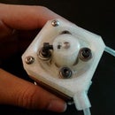
Step 12: Hub Mounting


Attach the hub to the motor as shown. Do not forget the washer.
Step 13: Electronics- RPM Sensor


Attach the RPM sensor as shown (nuts not necessary, the plastic should be threaded). Use a piece of tape to block half of the sensing area to block the IR light being emitted.
Adjust the sensor position until it is about 3mm from the motor. Lock the position by tightening the mounting screws.
Step 14: Lid Assembly


To assemble the lid, first attach the front and back plates of the lid to the top plate of the lid.
Step 15: Lid Assembly


Attach the side plates of the lid, they are identical. Screw the lid together.
Step 16: Electronics- Safety Switch


First thread the socket end of the touch switch through the slot in the base plate as shown in the picture.
Mount the switch. Before fully tightening the screws, slide the switch position so that it triggers when the lid is closed.
Step 17: Frame Assembly- Lid


Attach the lid to the hinge plates on the back of the frame. Use lock nuts instead of regular nuts and take care not to fully tighten the screws so that the lid freely rotates.
Step 18: Electronics- Wires


Simply attach the wires as shown. If desired, zip-tie unruly wires using the mounting holes in the left frame plate.
Step 19: Frame Assembly- Bottom Plate


Attach non-slip pads to the bottom plate in the configuration shown. Then attach the plate to the frame as shown.
Step 20: DONE!
That's it! Your centrifuge should be fully functional. Charge your batteries and take it for a spin (no pun intended).

Third Prize in the
Build My Lab Contest

Participated in the
Microcontroller Contest


