

Introduction: Talking Pumpkin


So my boss came to me one last week and said he wanted to scare the trick-or-treaters who came to his home, and the kids who would come to work during a special Halloween Walk the community does. Thus was born the talking pumpkin.
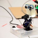
In short, I used an Arduino, an SD card read/writer, and an ultrasonic sensor to trigger a sound byte when the kids walk past our pumpkin… something they would not expect.
If you just want to download the code, and wire it up, skip ahead to step 4. Otherwise, just continue reading in order.
Step 1: Parts List


[1] Arduino Uno
[1] SD card module (about $1.50 on Ebay)
[1] Ultrasonic HR-SR04 (about $1.50 on Ebay)
[1] Single pole single throw switch ($.50 Radio Shack)
[1] 3.5 mm mono female solder-type audio connector (about $1 from local store)
[1] Class 4, 4GB, SD card (from my camera)
[1] Mini Breadboard (from previous projects)
[1] Enclosure (I had mine laying around)
[1] 9volt battery connector ($.50)
Various resistors, wires, and capacitors (less than $5 from previous projects)
For less than $30 total you can get all the parts. Chances are that you have most of these things lying around, especially if you have previously worked with the Arduino or Raspberry Pi platforms. I spent a total of $1 for the 3.5 mm jack. The rest I had on hand.
Step 2: Distance Sensor (first Real Step)

The first step is to get the distance sensor working. There are lots of tutorials to follow to get it running. There is one that is easy to follow on the Arduino site. The code is as follows: (directly out of the built in examples)
/* Ping))) Sensor
This sketch reads a PING))) ultrasonic rangefinder and returns the
distance to the closest object in range. To do this, it sends a pulse
to the sensor to initiate a reading, then listens for a pulse
to return. The length of the returning pulse is proportional to
the distance of the object from the sensor.
The circuit:
* +V connection of the PING))) attached to +5V
* GND connection of the PING))) attached to ground
* SIG connection of the PING))) attached to digital pin 7
http://www.arduino.cc/en/Tutorial/Ping
created 3 Nov 2008
by David A. Mellis
modified 30 Aug 2011
by Tom Igoe
This example code is in the public domain.
*/
// this constant won't change. It's the pin number
// of the sensor's output:
const int pingPin = 7;
void setup() {
// initialize serial communication:
Serial.begin(9600);
}
void loop()
{
// establish variables for duration of the ping,
// and the distance result in inches and centimeters:
long duration, inches, cm;
// The PING))) is triggered by a HIGH pulse of 2 or more microseconds.
// Give a short LOW pulse beforehand to ensure a clean HIGH pulse:
pinMode(pingPin, OUTPUT);
digitalWrite(pingPin, LOW);
delayMicroseconds(2);
digitalWrite(pingPin, HIGH);
delayMicroseconds(5);
digitalWrite(pingPin, LOW);
// The same pin is used to read the signal from the PING))): a HIGH
// pulse whose duration is the time (in microseconds) from the sending
// of the ping to the reception of its echo off of an object.
pinMode(pingPin, INPUT);
duration = pulseIn(pingPin, HIGH);
// convert the time into a distance
inches = microsecondsToInches(duration);
cm = microsecondsToCentimeters(duration);
Serial.print(inches);
Serial.print("in, ");
Serial.print(cm);
Serial.print("cm");
Serial.println();
delay(100);
}
long microsecondsToInches(long microseconds)
{
// According to Parallax's datasheet for the PING))), there are
// 73.746 microseconds per inch (i.e. sound travels at 1130 feet per
// second). This gives the distance travelled by the ping, outbound
// and return, so we divide by 2 to get the distance of the obstacle.
// See: http://www.parallax.com/dl/docs/prod/acc/28015-PING-v1.3.pdf
return microseconds / 74 / 2;
}
long microsecondsToCentimeters(long microseconds)
{
// The speed of sound is 340 m/s or 29 microseconds per centimeter.
// The ping travels out and back, so to find the distance of the
// object we take half of the distance travelled.
return microseconds / 29 / 2;
}
Once you get this working you are well on your way. Check the serial monitor to make sure everything is working well.
Step 3: SD Card Music Player

This part was taken from a great tutorial found at http://apcmag.com/arduino-project-5-digital-audio-player.htm. Note that you do need to replace the current SD card class, as far as I can tell, it doesn't harm other projects, but I have not done extensive tests. If you are worried about changing the class, you can always add this to your libraries as SD2 instead.
Step 4: Putting It Together, Part 1

If you skipped right to this step follow the following step. Otherwise, skip to the next step.
We’ll need the ‘tmrpcm’ and a modified ‘SD’ card library. You’ll find these in the zip file you can download from apcmag.com/arduino.htm (look under the Project 5 heading). Copy the ‘SD’ and ‘tmrpcm’ folders to the ‘libraries’ folder in your Arduino IDE folder (yes, overwrite the original ‘SD’ library) and restart the IDE if you’ve had it running already.
The ‘apc_05_audioplayer.ino’ file is our sketch, which ties everything together. It boots up the Arduino, turns on the SD module, checks the card and waits for you to press the button. Press it for less than a second and it’ll load and play the first file. If you press the button again for less than a second, it’ll pause playback; pressing it again resumes playback. Press it for more than a second, and it’ll automatically skip forward to the next audio track and begin playback. There are no volume controls — you adjust this at your amplified speakers.
Unfortunately, the ‘tmrpcm’ library creates a pop whenever a track stops or starts. A low-pass filter will help a little, but it’s caused by the PWM signal turning on and off. (Qutoed from http://apcmag.com/arduino-project-5-digital-audio-player.htm)
Step 5: Putting It Together, Part 2

I took some time, eliminated some unnecessary parts of the code, and added in a distance measurement that triggers on a certain distance. Here is the code:
/*
HC-SR04 Sensor Portion
https://www.dealextreme.com/p/hc-sr04-ultrasonic-sensor-distance-measuring-module-133696
This sketch reads a HC-SR04 ultrasonic rangefinder and returns the
distance to the closest object in range. To do this, it sends a pulse
to the sensor to initiate a reading, then listens for a pulse
to return. The length of the returning pulse is proportional to
the distance of the object from the sensor.
The circuit:
* VCC connection of the sensor attached to +5V
* GND connection of the sensor attached to ground
* TRIG connection of the sensor attached to digital pin 2
* ECHO connection of the sensor attached to digital pin 4
Original code for Ping))) example was created by David A. Mellis
Adapted for HC-SR04 by Tautvidas Sipavicius
SD Card reader & Player Portion
DO NOT USE CLASS-10 CARDS on this project - they're too fast to operate using SPI
Created by NorseEngineering October 2013
*/
#include //This is the modified SD Library.
#include
TMRpcm tmrpcm;
File root;
File entry;
// set chipSelect to '10' if using the $2 SD card module or '4' if using the
// Ethernet shield's microSD card instead.
const int chipSelect = 10;
const int oldCard = SPI_HALF_SPEED;
const int newCard = SPI_QUARTER_SPEED;
const int trigPin = 2;
const int echoPin = 4;
const int led = 8;
//The distance below which the sound triggers (in feet). Must be an integer
const int DISTANCE = 6;
//Duration of the LED on phase.
const int CLIP_DURATION = 10000;
//Refresh rate for the sensor.
const int RATE = 10;
// set cardType to 'oldCard' if using an old SD card (more than a few years old) or
// to 'newCard' if using a newly-purchase Class-4 card.
int cardType = oldCard;
int wasPlaying = 0;
int inSwitch = 7;
int finished = 0;
int start = 0;
int pauseOn = 0;
unsigned long timeDiff = 0;
unsigned long timePress = 0;
void setup() {
Serial.begin(9600);
pinMode(led, OUTPUT);
Serial.print("\nInitializing SD card...");
pinMode(chipSelect, OUTPUT);
if (!SD.begin(chipSelect,cardType)) {
Serial.println("failed!");
return;
}
Serial.println("done.");
tmrpcm.speakerPin = 9;
pinMode(inSwitch,INPUT_PULLUP);
digitalWrite(inSwitch,HIGH);
root = SD.open("/");
}
void loop(void) {
long duration, inches, cm, feet;
pinMode(trigPin, OUTPUT);
digitalWrite(trigPin, LOW);
delayMicroseconds(2);
digitalWrite(trigPin, HIGH);
delayMicroseconds(10);
digitalWrite(trigPin, LOW);
pinMode(echoPin, INPUT);
duration = pulseIn(echoPin, HIGH);
inches = microsecondsToInches(duration);
cm = microsecondsToCentimeters(duration);
feet = microsecondsToFeet(duration);
Serial.print(feet);
Serial.print("ft, ");
Serial.print(inches);
Serial.print("in, ");
Serial.print(cm);
Serial.print("cm");
Serial.println();
//Meat of the code here in this if statement.
if(feet < DISTANCE )
{
playNext();
delay(CLIP_DURATION);
}
delay(RATE);
digitalWrite(led, LOW);
}
void playNext() {
digitalWrite(led, HIGH);
entry = root.openNextFile();
if (entry) {
entry.close();
tmrpcm.play(entry.name());
wasPlaying = 1;
Serial.print("wasPlaying = ");
Serial.println(wasPlaying);
} else {
if (wasPlaying == 1) {
Serial.println("Completed playback.");
wasPlaying = 0;
finished = 1;
start = 0;
root.rewindDirectory();
}
}
}
long microsecondsToInches(long microseconds)
{
return microseconds / 74 / 2;
}
long microsecondsToCentimeters(long microseconds)
{
return microseconds / 29 / 2;
}
long microsecondsToFeet(long microseconds)
{
return microsecondsToInches(microseconds) / 12 ;
}
I also added a switch to the first row of the breadboard that interrupts the 9 volt supply to the breadboard, so that I didn't have to open the case to turn if on and off.
Also the code is here is a text file.
Attachments

Step 6: The Outcome
Here are a couple of videos that show the end result. I sprayed the case black to hide it in the pumpkin in the dark. I also handmade some connectors to try and save some space, as it is at a premium in my small case. You can leave it as nice or as messy as you want.
In the first, the sound is an alarm sound. It was the only WAV I had on hand. For later iterations, we have other WAVs. If multiple are on the card, the code will go through them one by one, triggering the new one when the next person walks by.
The second video is a plastic pumpkin on my doorstep. The second time I walked by it lights up but no audio. I did this so that when the trick or treaters are leaving it won't speak again. After that, fair game again!
Step 7: Final Thoughts
Instead of putting this in my rotting pumpkin, I put it instead in my plastic pumpkin.
This project would easily benefit from an external battery, giving it a longer up time. Right now it lasts about 3 hours.
In the future I have plans to put this to a camera so that when someone walks by, it takes and sends a picture to the user to allow them to know who or what is in the house.
I've found that putting a schematic in the project helps me know what I did when I go and open my projects months later. It is up to you if you do, but I would suggest it.
There are many other things that can be done with sound and a distance trigger sensor. Let your imagination run wild.
Attachments

Participated in the
Make It Glow Contest

Participated in the
Microcontroller Contest

Participated in the
Pumpkin Contest


