

Introduction: PC Power 12 V Current Limiter


To safely power something from your PC, the attached loads have to be limited to a safe current in order to avoid the chance that a short circuit might cause inadvertent shutdown and damage to your data. This circuit can be used to safely bring out the 12V line from your computer to supply a limited amount of current to power external gadgets.
With normal loads, the power transistor is in saturation and so the regulated +12V line is directly available (minus only the Vcesat of the PNP transistor). If the output is accidentally shorted, the npn transistor turns off and removes the base drive of this transistor.
This circuit is intended for protection from short circuits. It might be possible to apply a load that brings the series transistor out of saturation without removing base drive to it: such a situation will cause heating and might cause it to fail short-circuit. Those who wish to draw significant current from this circuit will be well advised to check that the transistor is indeed in saturation with their intended load.
That said, this is a simple way to draw a few tens of milliamps at 12 V from your PC without danger to either load or the PC.
Step 1: The Circuit

Any electronic project starts with a circuit. This one has a PNP power transistor in series with the +12V line from the PC. The collector supplies the external circuitry.
A small signal NPN transistor is fed with the output voltage through two resistors connected as a potential divider. Should the output voltage become less than a certain value, this transistor will turn off.
The collector of this transistor supplies the base current of the power PNP transistor. So the two transistors will always switch on or off together.
The power transistor (BD140) is supplied with a certain current via the green LED and 470 ohm resistor. It has a certain gain, around 50 or so, and its collector can supply only the gain times base current before it drops voltage (comes out of saturation).
So the maximum current draw can be changed by appropriately dimensioning the base resistor of the PNP power transistor.
The voltage divider at the output determines the voltage at which the current supplied by the transistor drops to zero.
The 470 ohm resistor in parallel with the PNP transistor supplies a certain amount of current so that the circuit will switch on when first powered on.
Step 2: Costruction: Board and Connector

A power connector was salvaged from a 3.5" floppy drive. A scrap of copper clad board was dug up from somewhere.
A piece of board slightly wider than the connector was cut to size, edges smoothed and holes drilled to accept the connector.
Step 3: Soldering

The pictures show the connector before and after soldering. The middle two pins are ground. One outer pin is +5 V, which we do not use. The other outer pin is the +12 V we want to use.
The two pins carrying voltage will be isolated by cutting the copper after soldering.
I find that doing things this way allows freehand cutting, because the dimensions are evident after the component is on the board.
Step 4: Mark the Diagram

The diagram has been marked with the components already fitted. This is a great aid in constructing a circuit. You go on soldering and marking, and when you run out of things to mark on the circuit diagram your circuit is probably complete and ready for the first cycle of crashing and burning.
Step 5: Solder Components

The copper on the board has been cut to isolate the live pins and bypass capacitors soldered on. We are not using the +5V line at present, but I fitted a capacitor there anyway.
And the circuit diagram has been marked up to reflect the components on the board.
Step 6: Solder Some More Components

The components around the small transistor has been fitted. The one pictured is not the BC147 in the diagram, it was rescued from some board that had reached the end of its active service and had been thrown away. Like the rest of the components.
In order to know where to cut, the components are first placed on the board, their outline traced, and lines drawn around the perimeter of the desired conductor pattern.
Two closely spaced parallel lines are scored on the copper with a sharp knife, and the thin strip of copper in between peeled away resulting in an insulating channel.
No chemicals are used at all.
Then the components are soldered in, and again the board marked and cut.
I term this "cut and go" because the knife and soldering iron work alternately on the same board.
The circuit diagram has been updated to reflect the components placed on the board. I could get only a 2K0 chip resistor. A calculation resulted in the revised value for the top of the voltage divider - the 10K was changed to 36K, so that the transistor will stop conducting if the voltage drops slightly from the 12V nominal output.
Step 7: Update the Diagram

Mark the diagram in order to match the progress of your work. Make this a habit, as it is easy to overlook a vital component in the heat of the soldering and then spend ages searching for the cause of the resulting malfunction.
I decided to add one more LED to monitor the operation of the circuit. A green one to light when all was hunky-dory and a red one to light when bloopers!!!
A resistor value was also changed, and this has been marked on the circuit diagram.
Now only the power transistor is left to be fitted. Some functional checks were made to ensure that it will all work and not go up in smoke.
Step 8: Test It

All components are now on board and it was tested. Another component change was necessary before it would work. That resistor at the output, originally 10K, changed to 36K, had to be changed to 22K.
With the original 10K, the onset of current limiting was too high - I could draw more than 600 mA from it.
With 36K, it would not turn on when connected to the intended load, a video camera. By trial and error, I determined that 22K would be OK.
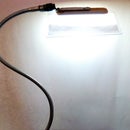
The current limit on my prototype was around 220 mA. If the output was short circuited the current fell to about 16 mA. The circuit was judged have fulfilled its design target and will shortly be fitted to my PC. I intend to power a video camera with it. The camera draws around 100 mA. It is at the end of a long cable with many joints (split from flat cable) which occasionally suffers from short circuits.
Step 9: The Annotated Diagram and Pictures


I present the circuit diagram and photos labelled for cross reference.
I have made a circuit board layout in case somebody out there wishes to etch a board in the traditional way. The layout is attached as a pdf file, and the overlay as a gif image.


