

Introduction: PIR Alarm Arduino Motion Sensor (with Encasing)
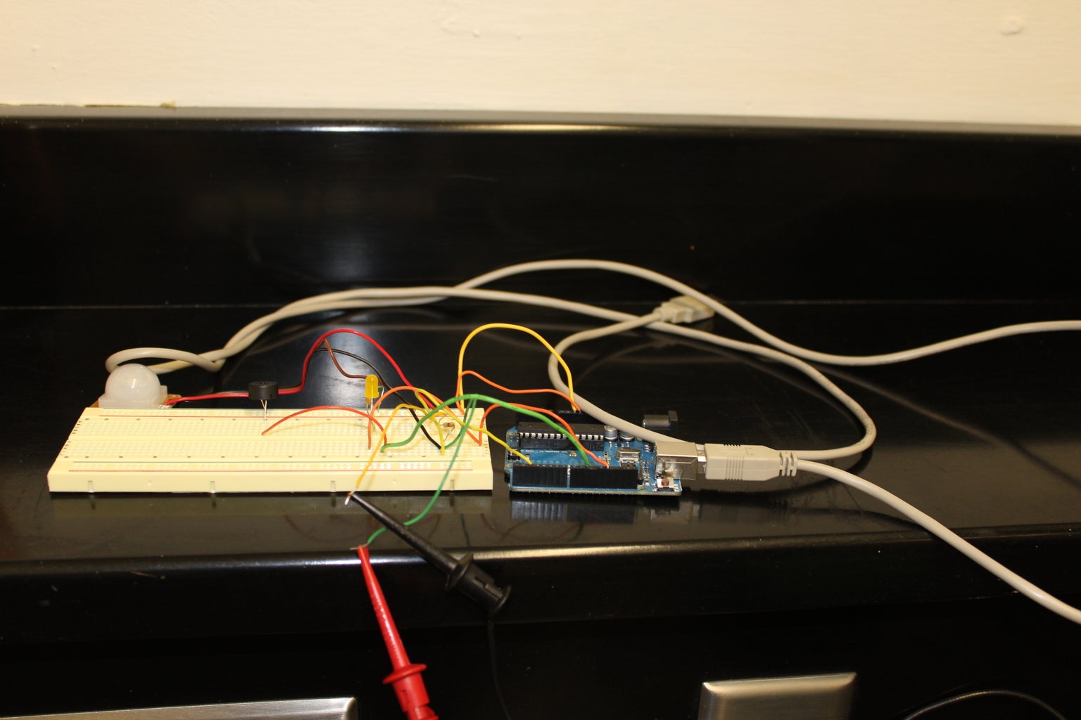
This is a guide on how to make a motion detector with an arduino! Enjoy!
Step 1: Items Needed
Arduino Uno microcontroller
Breadboard, Mini
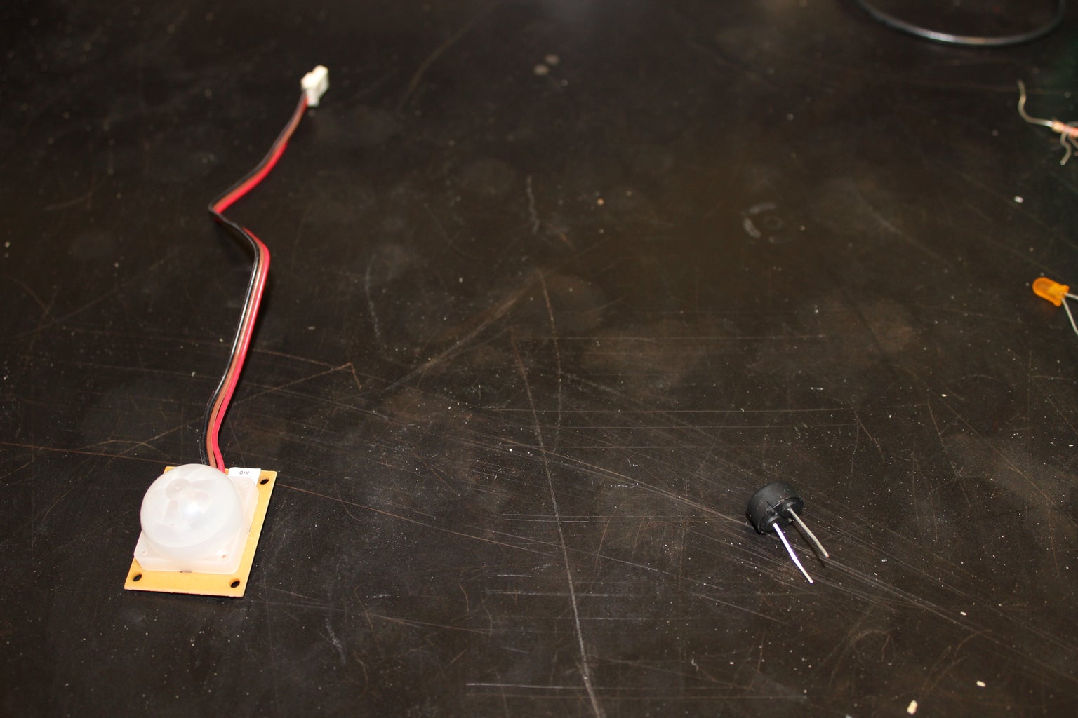
PIR sensor, SE-10
Jumper wires
Piezo Buzzer
LED, any size or type
Plywood(optional)
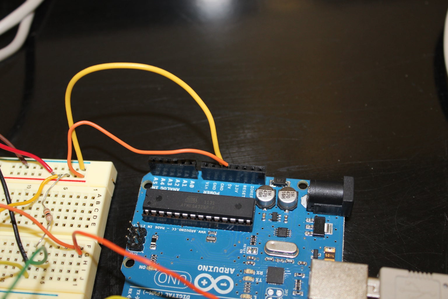
Step 2: Wire the Arduino to the Breadboard
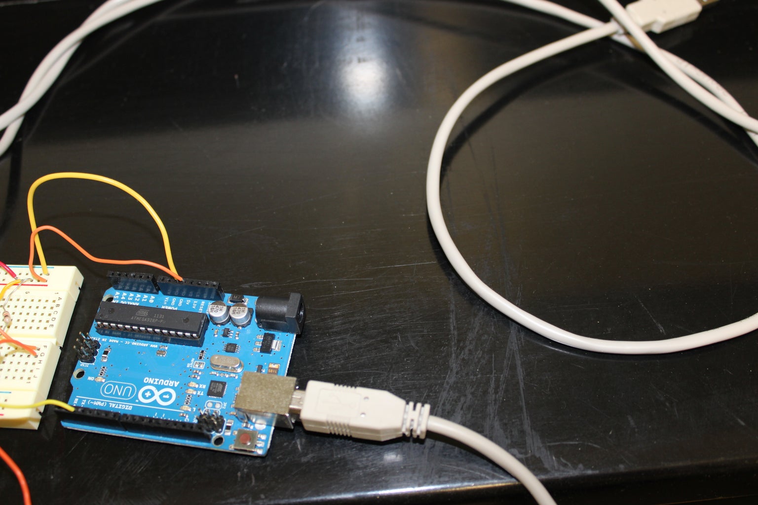
Connect Digital 2 (on the Arduino), 5V, and GND, each, to a different row on the breadboard.
Step 3: Plugging in PIR Sensor
Plug the PIR sensor into the board so that -,+, and Out connect to GND, 5V, and Digital 2. Make sure to place a 10K pullup resistor between the signal (Out) and 5V (+).
Step 4: Plug in the LED
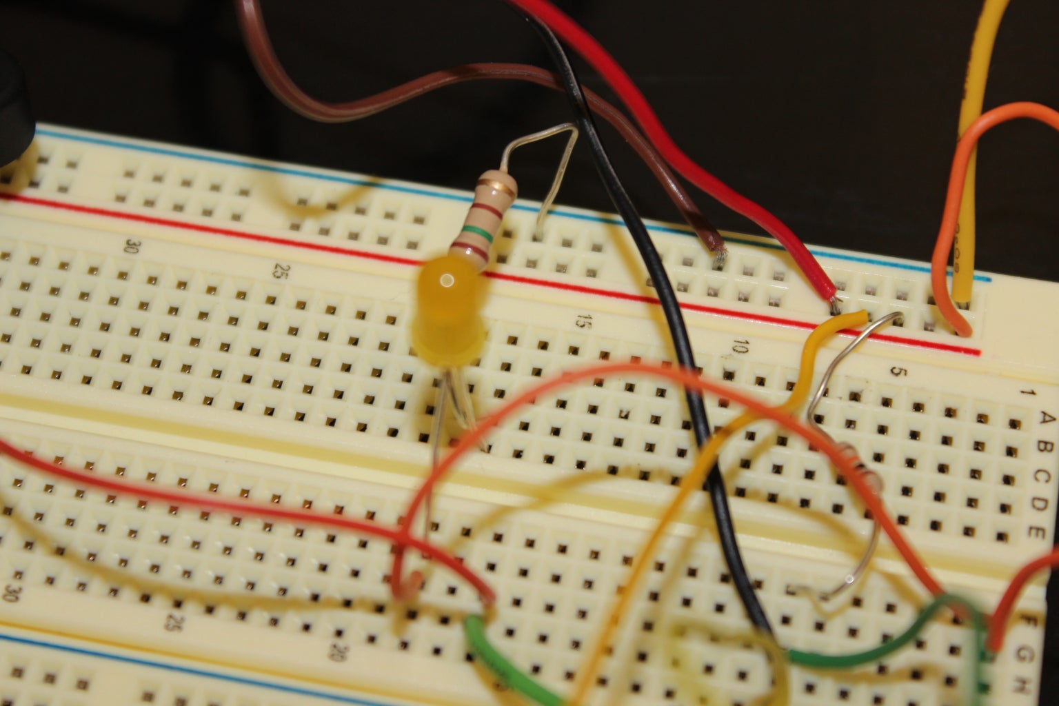
Connect the anode (the longer leg) into digital pin 13 on the Arduino Uno. Plug the cathode (the shorter leg) into GND. WARNING: Be sure to place a resistor (150-170 Ohm) between the LED and GND.
Step 5: Connect the Piezo Buzzer to the Arduino
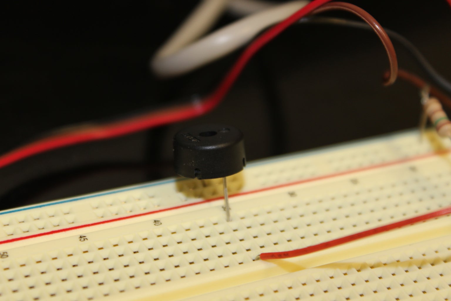
Connect the Piezo buzzer to digital pin 10 and GND. The way in which the piezo buzzer does not matter since the polarity of the buzzer does not matter.
Step 6: Launch Arduino Software
int pirPin = 2;
int pinSpeaker= 10;
int ledPin = 13;
void setup(){
Serial.begin(9600);
pinMode(pirPin, INPUT);
pinMode(ledPin, OUTPUT);
pinMode(pinSpeaker, OUTPUT);
}
void loop(){
int pirVal = digitalRead(pirPin);
Serial.println("starting to read PIR");
analogWrite(ledPin, 0);
delay(2000);
if(pirVal == LOW) {
analogWrite(ledPin, 255);
Serial.println("Motion Detected");
tone(10, 700, 100);
delay(2000);
}
}
void tone(long duration, int freq) {
duration *= 1000;
int period = (1.0 / freq) * 1000000;
long elapsed_time = 0;
while (elapsed_time < duration) {
digitalWrite(pinSpeaker,HIGH);
delayMicroseconds(period / 2);
digitalWrite(pinSpeaker, LOW);
delayMicroseconds(period / 2);
elapsed_time += (period);
}
}
Step 7: Build Encasing (optional)
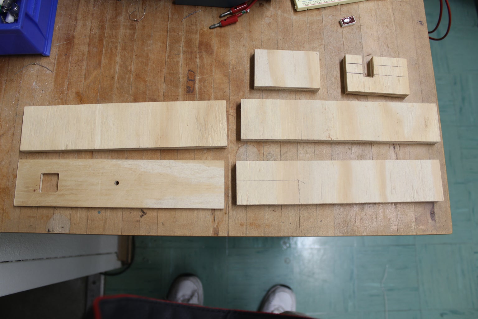
Step 1: Use a bandsaw to cut plywood into two 10X2.5 INCH pieces
Step 2: Use a bandsaw to cut plywood into two 10X 2 INCH pieces
Step 3: Use a bandsaw to cut plywood into two 3.25X2 INCH pieces
Step 4: Use a bandsaw to create a 1.25X0.60 INCH cutout into one of the 3.25X2 INCH pieces. Be sure to create this cutout in such a way that allows for access in the USB port of the Arduino Uno.
Step 5: Use a mill to cut a 0.935X0.935 INCH hole into one of the 10X2.5 INCH pieces. This hole is where the PIR sensor is inserted. NOTE: Depending on the PIR sensor used, the size of the hole may vary.
Step 6: Use a mill to drill a a hole equal in diameter to LED used and insert LED here.
Step 7: Use small amount of epoxy to attach breadboard and Arduino Uno to a 10X2.5 INCH piece.
Step 7: Assemble encasing using epoxy.
Step 8: YouTube Video of Finished Project (Parts 1 and 2)
http://www.youtube.com/watch?v=Jd-CCZi_Gho
http://www.youtube.com/watch?v=6EtK16YYmzI&feature=relmfu


