Introduction: PVC Water Pump


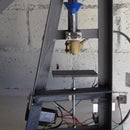

Build a long reach pvc water pump, handy for pumping right down to the bottom, and easily transfer water between rain barrels without resorting to the small plastic 5 litre paint buckets that fit the opening.
I had hoped that this small scale pumping windmill copy would start siphoning once I pulled the plunger past the T piece, alas the reducing internal diameter of the T is smaller than the internal diameter of the 50mm pvc pipe which makes it difficult to pull the plunger past the T.
Experiments have shown that the standing water level needs to be halfway up the inlet pipe, roughly 500mm high for the syphoning action to occur.
A check valve, made out of a hollow plastic ball found in roll-on deodorants, right at the bottom of the inlet pipe, ensures that you dont have to pull on the plunger like a stark raving lunatic in order to raise water.
~Now updated with a better valve~
Step 1: Parts

Not a whole lot of tools needed, I used a hacksaw, pliers, soldering iron and a M5 die for threading the 5mm steel plunger rod.
In addition you will need,
- 2 Metres of 50mm pvc pipe and suitable pvc solvent for the joints.
- 1 x 50mm solvent T piece. grey colored pool pvc fittings preferred
- 1 x 50mm 90 degree solvent bend. grey colored pool pvc fittings preferred
- 1 x 50mm solvent end cap. cut a disk out of this for the plunger backing plate
- 1x plastic ball from a roll-on deodorant. mine was a 35mm mitchum roll-on ball. Not needed if using updated butterfly valve
a short length of thin wire used as a ball valve retainer to keep the ball near the seat when not sealing.Not needed if using updated butterfly valve
- The updated butterfly valve will need a bit of duct tape, a disc of stainless steel and a brass rod for the valve pivot.
leather, enough for 2 x 50mm dia discs. 1 for the plunger and 1 in the cap used as a rod shaft seal.
- 1 x 50mm steel disc for the leather retainer in the top cap
- 50cmm 5mm steel rod. piece of recycled trellis.
- 2 x M5 nuts for plunger.
- 1 x top cap, a 50mm solvent end cap can be used but dont glue it on. I happened to use a cap from a can of shaving cream which was a good friction fit.
I used 105cm for the inlet, 20cm for the outlet cross piece and 75cm for the outlet down piece, I had a 40mm scrap piece for the join between the top cap and T piece.
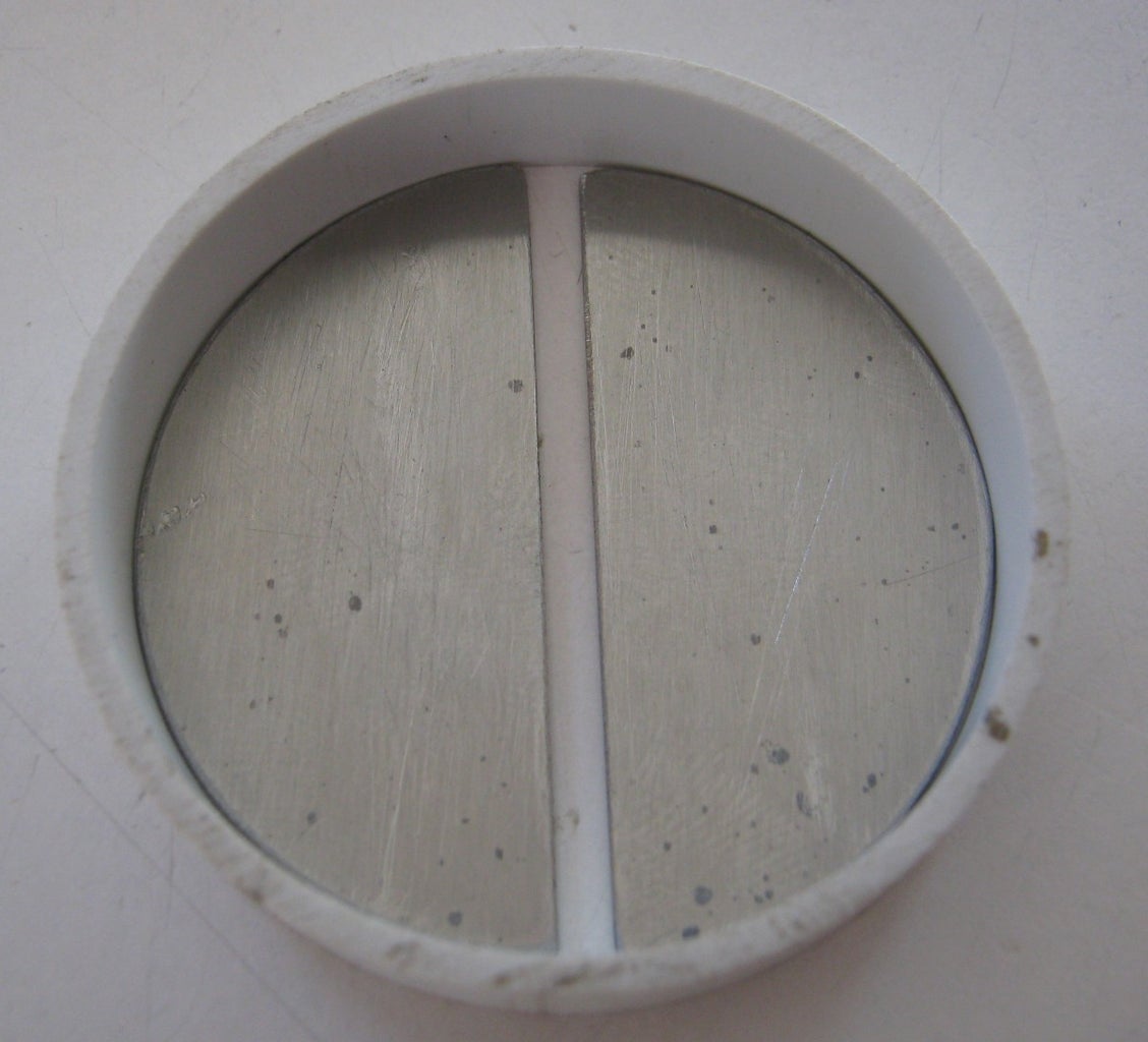
Step 2: Full Flow Butterfly Valve


The check valve at the bottom is key to ease of use otherwise you'll land up yo-yo-ing with a 1.5 kg column of water, there's more efficient ways of heating water, so its kinda pointless even on a slow day.
Some thought on the matter of valves led me to this design, a double flapper butterfly valve, with a visible difference in water volume discharge.
I used a section of a 2mm brass brazing rod with duct tape as both the hinge and valve seat seal. Taking into account the weight of the full column of water, roughly 1.9kg's, makes plastic or rubber impractical and so I settled on a disc of 0.9mm stainless steel which I then cut in half to act as the valve body.
My sequence of assembly
- drill the pvc pipe and insert the brass valve pivot.
- halve the ss disc and add clearance for the brass rod, roughly 5mm should work.
- use a slice of pipe to align the 2 disc halves, a bit of masking tape keeps them from shifting around while you lift off the aligment slice and apply duct tape.
- insert the ss duct tape flap from the inlet side of the pipe.
- lastly insert the pvc slice valve seat and glue with solvent.
If you got the order wrong just swop ends no great problem. Before glueing in the pvc seat ring, sand it flat removing saw maks for a better performing valve.
I intentionally didnt allow the valve flaps to open perpendicuarly to maximise the opening due to the possibility that the downward flow of water wouldn't close them back against the valve seat, or might delay in doing so.
The new valve flows better and seats quieter than the old roll-on ball version.
Step 3: Plunger and Flap Valve


This draws the water column up the inlet pipe, the leather flap and disc holes makes it easier to push the plunger rod down for the next power stroke.
I used a rod 50cm long, shorter would also work but you would need more power strokes to do the same work.
Step 4: Top Cap and Rod Seal


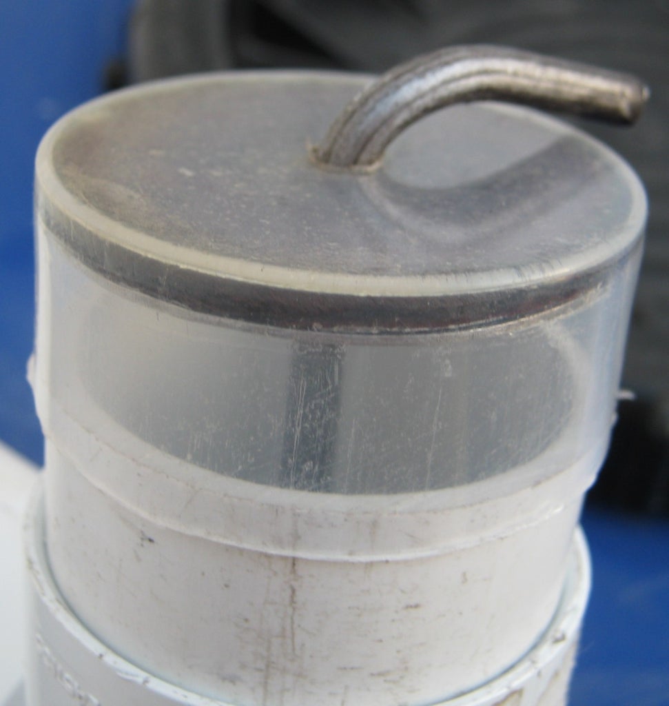

I wanted the shaft to be sealed but didnt want the drag of rubber so settled on leather squashed against the cap with a SS disc, no doubt thick plastic could also be used.
I usually start with short quick power strokes in the beginning to overcome the tendency of the water column to drop back down while there is still a lot of air in the inlet pipe. Once the water reaches the T piece then its relatively easy during a power stroke which displaces a fair amount of water.
Step 5: Free Flowing T-piece


I have since modified the first version with a free flow pvc fitting from the pool hardware section, thinking that it was the reason why the pump didn't start syphoning, but once the standing water level is halfway up the inlet pipe then rapid power strokes to get the column of water moving results in the pump syphoning, a quick full length pull on the plunger and it seats in the top of the T piece out of the water flow allowing the syphoning action to continue.
It works much better and its easier for the plunger to travel to the top, Ive attached a pic with the 2 T pieces side by side, the grey T is the pool hardware version and the white one is a general outdoor waste plumbing fitting.
Usually the pool pvc fittings are more robust with thicker walls and better flow capabilities than the waste fittings so I prefer to use them, but its not essential if they arent available.
Step 6: Roll-on Ball Check Valve~NOW RETIRED~
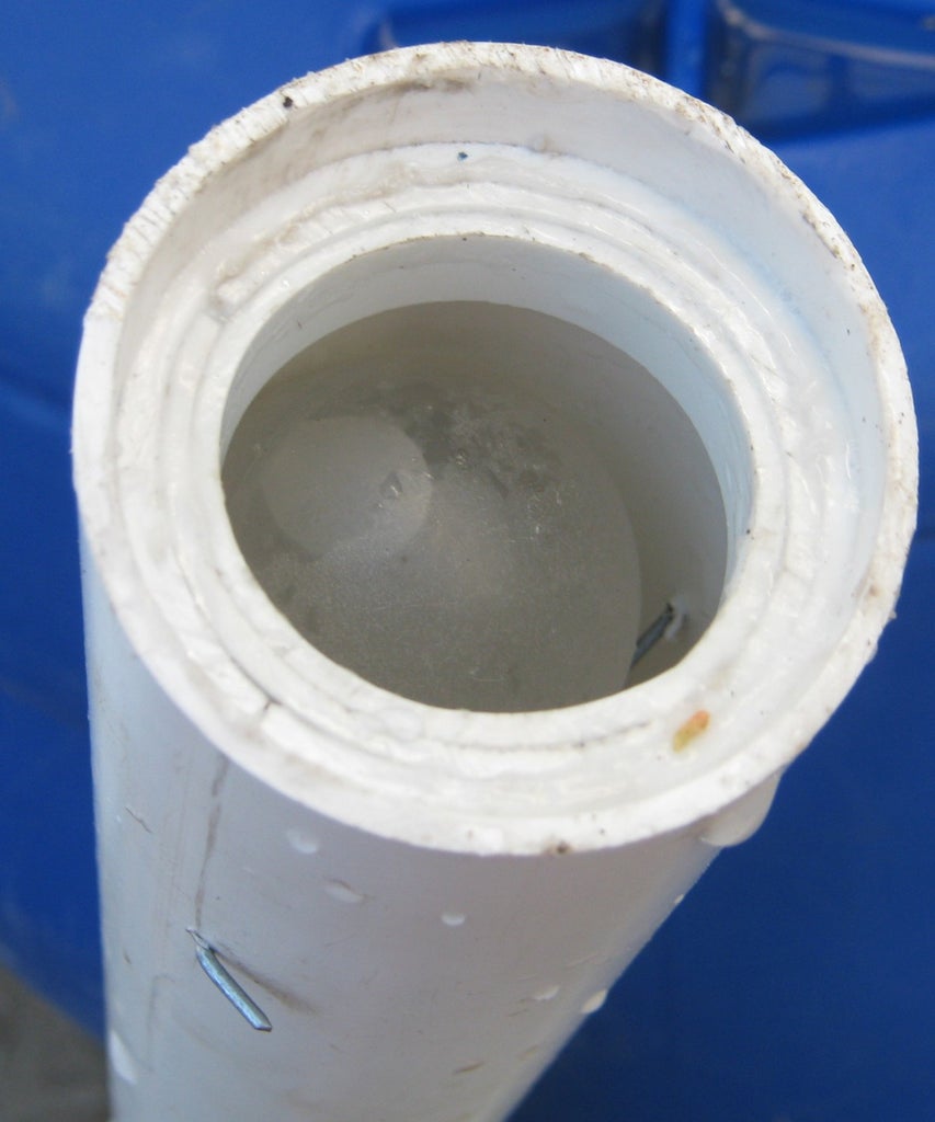


I created the ball seat from sections of scrap pvc, small gaps are ok, and then inserted the ball from the top.
The plastic ball was drilled with a 3mm drill bit to fill with water to keep a neutral buoyancy and then I melted the hole closed using off cut scraps from the shaving cream can cap.