

Introduction: Paper Motorized Walking Machine "Sculpture"


In this Instructable I show how I created a motorized "walking machine/sculpture" made out of paper. I will be taking you through all the stages from concept to design and all the way to the end of the build. This will hopefully be sufficient enough to act as a guide if you choose to create and improve on your own version.
Disclaimer: At the end of the creating this whole thing I realized that the way I designed the motor section did not have enough torque. So it is unable to walk but If I were to redesign the motor section using a gear combination with a higher torque then it would walk. You could technically call it a motorized sculpture now.
Step 1: Materials

These are the materials that I used during this build.
- Card Stock (I used 110lb heavyweight from Staples)
- Standard printer paper
- Cutting mat
- Hobby knife
- Scissors
- Pencils
- Protractor
- Metal ruler
- Plastic ruler
- Masking tape
- Scotch tape
- Super glue
- Bottle of all purpose white glue
- Tooth picks
- Wooden skewers
- Drinking straws
- D/C hobby motor
- Pulleys (one small, one large)
- AAA battery holder
- Push button on/off switch
- Wires
- Rubber band for pulleys
Step 2: The Idea


The idea was inspired from the works of of a Dutch artist named Theo Jansen who created these large walking sculptures called StrandBeests.
What are StrandBeests?
"Self-propelling beach animals ... consists of recycled plastic bottles containing air that can be pumped up to a high pressure by the wind. This is done using a variety of bicycle pump, needless to say of plastic tubing. Several of these little pumps are driven by wings up at the front of the animal that flap in the breeze. It takes a few hours, but then the bottles are full. They contain a supply of potential wind. Take off the cap and the wind will emerge from the bottle at high speed. The trick is to get that untamed wind under control and use it to move the animal. For this, muscles are required. Beach animals have pushing muscles which get longer when told to do so. These consist of a tube containing another that is able to move in and out. There is a rubber ring on the end of the inner tube so that this acts as a piston. When the air runs from the bottles through a small pipe in the tube it pushes the piston outwards and the muscle lengthens. The beach animal's muscle can best be likened to a bone that gets longer. Muscles can open taps to activate other muscles that open other taps, and so on. This creates control centres that can be compared to brains."
- Jansen
What really intrigued me was the way that they moved. Instead of using wheels, they used legs that were designed in such a way to simulate a smooth walking motion. The motion was almost hypnotizing to watch in an artistic way as well as at mechanical standpoint.
At that point, I wanted to try and make my own version of a walking sculpture/machine based off the Jansen's Linkage designs.
Step 3: Design


The overall design took its form from a rough sketch that I made. The body would have to allocate enough space to house the batteries and the motor inside, which can be seen in the third picture. The back end of the body would be where the battery holder would go and the the space left over in the front would contain the motor, as well as a spot for an on/off switch placed somewhere on the top.
The fifth image shows the dimensions of each linkage based on the numbers that Theo Jansen provided. I scaled the values down to create a smaller version.
The fourth image shows the design for the leg linkages which are pretty simple in shape.
Step 4: Motor: Design


Once I had the overall design finished I moved onto the motor design that would move the whole thing. With the parts that I had lying around my house I created the blueprint for the "engine".
When I finished the blueprint, I went ahead and started drawing out each individual part that would all come together and create the housing.
As noted in the introduction, if I knew that the pulley system would not supply sufficient torque, I would have designed the motor section to use a gear ratio instead. Sorry for any inconvenience as I always strive to make things work as they were intended to work.
The PDF files for motor housing can be found below.
Attachments

Step 5: Motor: Build Part 1


Now that I have all the pieces for the motor housing drawn out, I can start cutting out the pieces.
Step 6: Motor: Build Part 2


With all the pieces cut out, I started to group the pieces and glued them together.
When glueing the pieces together, I take regular white glue and spread it evenly on one side of a piece with a toothpick. Then I take another matching piece and layer it on top. once I have all the pieces layered, I place the completed pieces under a heavy textbook until it is fully dry, making it very strong and stable in the end. This technique is similar to making hardened paper.
Step 7: Motor: Build Part 3


Now I can start assembling the glued pieces together to create the full motor mount and axle assembly.
I started by putting the motor and the two inner supports together. Then I glued it to the base plate.
Step 8: Motor: Build Part 4


Next I assembled the axle and a pulley together and checked the fit on the motor mount.
After checking the axle, I took the front piece and glued it on.
Step 9: Motor: Build Part 5


Then I took the right side cover and glued it on.
Step 10: Motor: Build Part 6


I took the left side cover and glue it on next. Before glueing it on I placed the rubber band inside around the larger pulley.
Step 11: Motor: Build Part 7


I finally glued the top cover on to finish off the motor mount.
Step 12: Motor: Build Part 8

The last thing I did was create a hole on the top and bottom so I could feed the wires inside to the motor.
So that ends the motor build and the next step I went to was building the body.
Step 13: Body: Design


The design of body started to form its shape naturally after a couple sketches.
In the end the shape had to change a bit in order to fit the motor mount inside, so I had to raise the front part of the body up.
After getting the design of the body down, I went and started drawing the pieces that would eventually become the side panels.
I needed six layers for each left and right side panels.
You can find the PDF file below for the body side panels. Just print it off three times to get twelve layers in total.
Attachments
Step 14: Body: Build Part 1


Next I cut out all the pieces out for the side panels.
Step 15: Body: Build Part 2


With all the pieces for the side panels cut out, I started to group the pieces and glued them together.
Step 16: Body: Build Part 3


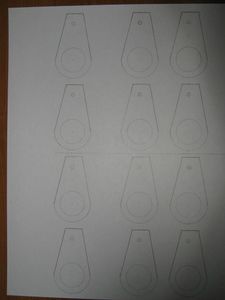
The next part I did what the crank shaft discs that would make the legs move.
I am doing this part now so I can align the side panels with respect to the discs.
The image/pdf is a bit faint but the diameter is 4cm and the distance from the centre to the outer hole is 1.5cm.
Each disc when completed will have twelve layers in total, so you are going to have to print the pdf twice.
Disclaimer: I had to change the distance of the holes from the centre of the disc. The distance is now 1/4 of an inch from the centre. You can see the change in image 5.
Attachments
Step 17: Body: Build Part 4


I trimmed the drive shaft first to the appropriate length before attaching the disks.
Next, I took the two crank shaft disks and super glue them to the drive shaft on the motor housing. Note that when attaching the disk, make sure that the holes near the outer edges are opposite of each other (the left sides hole would be in the reverse position on the right side).
With the crank shaft discs in place, I could now align the two side panels of the body.
Step 18: Body: Build Part 5


The next step was to take the rest of the body panels that went around the side panels and assemble them.
Here are the PDF files for them. There are diagrams which show where each body panel should go.
Step 19: Body: Build Part 6


I first took the panels that covered the back end area and glued them all together.
Step 20: Body: Build Part 7


Then I glued the assembled parts onto the main build.
Step 21: Body: Build Part 8


Next I put the battery holder into place and wired it to the motor and switch which can be seen in the next step.
Step 22: Body: Build Part 9


The next step was to install the switch and glue the remaining panels into their respective positions.
Step 23: Body: Build Part 10


For the battery cover I glued two toothpicks to the edges so that the cover would have a snug fit.
That ends the Body build section. Now it's time for the legs.
Step 24: Legs: Design


The design of the legs are a bit different when compared to the methods used to make the body and motor mount. Instead of creating layers for the legs I am folding the pieces into their shapes. I did plan to do the layering technique for the legs as well but when I cut the pieces for the first leg I found that there would clearance problems when the leg was in motion, so I had to figure out a new way to design the legs.
I did place image notes on the first image if you are unable to read the measurements.
In the third image you can see that there are red rectangles. anything in the red rectangles you do not need, so you can cut those out. The green rectangles indicate where one extra piece of card stock will go for structural purposes.
The PDF files for each part of a leg can be found below. You will have to print each file 4 times in total.
Step 25: Legs: Build Part 1


Starting off, I drew all the pieces out and cut them.
Step 26: Legs: Build Part 2


Next I creased all the places where they needed to be folded.
Step 27: Legs: Build Part 3


I took the top most part of a leg and super glued it together.
Step 28: Legs: Build Part 4


Then I took the mid section of one leg and glue it together. I glued an extra piece of card stock onto the right side seen in image 5 in order to make it stronger (or you can also see where to place the extra piece in image 4 which would be the green rectangle).
After I combined the two pieces.
Step 29: Legs: Build Part 5


Next I assembled the lower part of the leg and combined it with the rest of the leg assembly.
Step 30: Legs: Build Part 6


I then took a piece of a plastic straw and glued it to the bottom backside of the upper leg. I covered the straw with take as an extra support.
Step 31: Legs: Build Part 7


The final part of the leg also attaches to the crank disc. I assembled it in this step.
Step 32: Legs: Build Part 8

Do the same thing for another three times to get all the legs done.
Step 33: Final Assembly Part 1


Next I attached the wooden skewers to the main body and the crank shaft discs.
Step 34: Final Assembly Part 2


Then I took each pair of legs and attached them to the body.
Step 35: Final Assembly Part 3


To make sure that the legs did not fall off the crank shaft discs I took two small circular pieces of card stock (two layers each) and glued them to the tips of the skewers attached to the crank shaft discs.
Step 36: Finishing Up


Here is the finished product. If you have been following through the steps yours should be similar to the images you see above.
You probably have also noticed that I had to make a few changes here and there throughout this Instructable. Again I apologize if I causes any confusion.
If you have any questions or if things need to be clarified more, please do not hesitate to leave a comment and I will get back to you as soon as possible.
Thanks,
~ CreativLiMade
Step 37: Videos
Here are some videos to look at. The first video shows the legs in motion as well as a view of the whole thing around. The second video shows how it would work on a flat surface if the torque was a lot stronger.

Runner Up in the
Epilog Challenge VI

Participated in the
Battery Powered Contest

Participated in the
Glue Contest


