

Introduction: Perfboard Hackduino ($8 Arduino-compatible Circuit)


Never again will you have to dismantle a finished project just to reuse an Arduino board!
This tutorial will go through the steps involved in fabricating your own Arduino-compatible circuit using just ~$8 of parts (this includes the ATMega chip!). This is perfect for installing and embedding in permanent pieces, as you don't need to waste a full $30 Arduino board in a project you will never need to reprogram or touch ever again. It is also great because you can solder any custom circuits (LEDs, other ICs, any external analog circuit) on the same board, and customize in terms of shape and size.
I assume you have a regular Arduino board already, so pulling out the chip to reprogram it shouldn't be a big deal, since we're going for minimal parts here. You could even go simpler by leaving out the reset button! To better illustrate the process, I did all the wiring on top of the board for tutorial purposes, but feel free to save yourself some space and make some of the connections on the copper-clad side of the board, as seen on hackduino.org or similar.


Step 1: Gather Components and Tools


Parts list and buy links:
• 28-pin DIP IC Socket - $0.30 - buy mouser
• 16MHz crystal - $0.55 - buy mouser
• momentary push-button switch - $0.15 - buy mouser
• 1k ohm resistor - $0.05 - buy mouser
• LM7805 5v voltage regulator - $0.35 - buy mouser
• 2 x 22pF capacitors - $0.12 - buy mouser
• 10nF capacitor (ceramic disc code '103') - $0.10 - buy mouser
• 22uF capacitor - $0.02 - buy mouser
• ATMega168 or 328 microcontroller chip w/Arduino bootloader (you can use the one on your Arduino for now!) - $4.00-$5.50 - buy unbootloaded mouser(cheaper) / buy bootloaded sparkfun(expensive)
• breadboard style perf board - $1.45 from electronix express (elexp), or $1.99 - from radioshack
Total cost of components: $7.39 (!!!) *22AWG wire is not included
I have created a Mouser project that includes everything you will need, except for the perfboard itself (Mouser doesn't carry a good one at a good price). Also, this is the blank ATMega328 - so you will need to bootload the chip yourself. Also keep in mind that ordering in multiples makes everything cheaper! Here is the Mouser project.
Tools:
• IC Extraction Tool (you can use a min-flat head screwdriver to pop out chips as well) - buy
• Wire strippers
• Snips
• Multimeter
• Soldering Iron + solder
Step 2: IC Socket


First step is to figure out what exactly what you are putting into this circuit. For this tutorial all we will build, other than the ATMega necessities, is a voltage regulator, so I am leaving space at the top of the board for this. I also recommend leaving some space towards the bottom for a capacitor. However, if you know this will include much more than just the ATMega circuit, you should plan this out on your board now, and install the IC socket appropriately.
Most IC's (Integrated Circuits), and consequently their corresponding sockets, have a notch on one end. In this photo, you'll see the notch is towards the top of the board. This is extremely important to pay attention to both while building the circuit and when inserting the chip during the last step.
Go ahead and solder all 28 pins in, making sure the pins are sticking out of the copper side of the board.
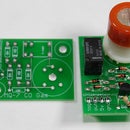
Step 3: Voltage Regulator


LM7805 circuit goes next. The 7805 allows you to power the circuit with a 9v battery or even 12v DC power supply, and ouputs 5v which is what our chip wants. With the "chair" facing you, solder the 10nF capacitor connecting the right two legs of the 7805. In this position, from left to right, the pins are input voltage - ground - output voltage (5v).
10nF cap (labeled 103) bridges the GND and OUTPUT voltage.
Step 4: Finishing the Power


I would never do this when actually building this circuit, but for tutorial purposes I felt it to be the clearest way to show you how I am taking power from the 7805 and sharing it with the board. In fact i recommend that you do not put any wires on top of the 7805 as it can heat up quite a bit, particularly if you are inputting more than 9v. Go around the 7805 on either side. Down the center of the perfboard you can see two rails that go down the center of board, which I am using as power rails (similar to the outer rails of a breadboard). I have chosen one to be ground, the other to be power (+5v).
From behind the 'chair' (7805) you can see I have taken the input voltage pin and ground to two terminals which is where our battery will plug in.
Lastly, install the 22uF capacitor across your power lines somewhere after the ATMega chip. In this case I am putting it at the end of my power rails. Be aware of polarity when using electrolytic capacitors - match the ground of the cap to the ground rail. This is important!
**if you haven't noticed by now, I ran out of red wire and am using blue for positive and the standard black for ground.
Step 5: Installing the 16MHz Crystal Oscillator


Now we begin building the ATMega circuit. I am attaching a diagram of every pin out of the ATMega8 series (also includes 168 and 328). You can see how important that notch is in terms of knowing what is what in a situation like this.
Pins 9 and 10 are labeled "crystal" - referring to our 16MHz oscillator. Polarity here doesn't matter go ahead and bridge the two pins with the crystal. With the board I am using, you can see each pin of the IC socket has 2 terminals bridged already. This is perfect here because we then need to add the 22pF capacitors and take those to what will be GND. For now just take them to the empty terminal slot, we will add GND here later.
Step 6: AREF, +5Vs, and GNDs


We will continue to build out our ATMega circuit by adding power and ground connections. As you can see in the Pin Mapping:
- GND needs to go to pins 8 and 22.
- VCC (+5v) needs to go to 7, 20, and 21 (the analog reference voltage).
Go ahead and connect these pins to the outer terminal pairs directly across from them, using the appropriately colored wire.
Step 7: Resistor to Reset Pin

This 1k ohm resistor connecting pin 1 to +5v will guarantee that the ATMega chip will never get accidentally reset.
By using a resistor and not wire, we have the option to add a button for resetting to this pin later.
Step 8: Connect GNDs and PWRs to the Rails


Now it's time to start actually connecting our leads to PWR and GND. I will use the power rails going down the board to my advantage and take leads from there.
**The way I am connecting these pins in this example is for tutorial purposes only. I want you to see exactly what I am connecting to where. If I were making a board for my own use, I would make these connections underneath the board directly to the power rails in the center. This can save lots and lots of space, but would be very hard to understand and follow in this tutorial. That being said, you can copy this exactly, and your circuit will work great! Just not the most space efficient method - get creative!
Step 9: Reset Button


**this step is optional -- you can leave the reset pin connected to +5v with the resistor, and your board will work perfecty**
For the reset button I am using a momentary push-button switch connected to GND. The kind I recommend has 4 legs, however there are only two you need to be concerned with. Using your multimeter check to see which pairs are redundant (meaning always connected, share the same line). When you press the button, both pairs get bridged, and GND is shared with pin 1, the reset pin, thus resetting the board.
Look at the rollovers to understand what i mean.
Step 10: Power Terminal : Battery/supply Connection


We are very close to finishing the circuit!
I have chosen to install female header pins to the input power supply terminals. This so that I can easily pop in and out any supply I want. However, for a board that will be going in to a specific project, it is a good idea to just permanently solder in your power supply. Perhaps it is a 9v battery clip. Or a DC wall adapter.
Now that we have finished soldering everything, use your multimeter to check continuity between the power rails. There should be no connection between the two. If the multimeter says there is go through and check for where there is a short. This could be harmful to the chip if we power it up and there is a short.
This is also a great time to check that your voltage regulator circuit is functional. Plug in your power supply and turn it on without the chip inserted into the socket. Use your multimeter to check that exactly 5v are running between the power rails. Because all of our power pins are connected to the rails, we know the chip will only receive 5v - just like we want.
Step 11: Program ATMega Chip W/Arduino and Extract


1. Program an Arduino, as you normally would. I am uploading code that flashes S-O-S in morse code on every digital pin. It is attached to this step. My version of hello world.
2. Using the IC extractor tool, slip both ends of the tool under either end of the chip. This can take a bit of fidgeting to wedge them under, but once they are, yank on it! The chip is often very secure in the IC socket, but you can't hurt it by pulling straight out after you have a secure hold on the chip.
3. I usually now replace the missing ATMega chip with the new chip ordered. Make sure it has the Arduino bootloader on it, though!
Here is the code in case you don't want to waste time downloading:
/*
S.O.S. morse code all LEDs!
Hello World for the Distressed Chip.
joe saavedra 2010
http://jos.ph
*/
int S = 1;
int O = 2;
void setup(){
for(int i=0; i<14; i++){
pinMode(i, OUTPUT);
}
}
void loop(){
flash(S);
flash(O);
flash(S);
delay(750);
}
void flash(int letter){
switch(letter){
case 1: //the letter 'S' !
dot();
dot();
dot();
break;
case 2: //the letter 'O' !
dash();
dash();
dash();
break;
}
delay(250); //break between each letter
}
void dot(){
for(int j=0; j<14; j++){
digitalWrite(j, HIGH);
}
delay(130); //length of dot
for(int j=0; j<14; j++){
digitalWrite(j, LOW);
}
delay(130); //space between dot
return;
}
void dash(){
for(int k=0; k<14; k++){
digitalWrite(k, HIGH);
}
delay(250); //length of dash
for(int k=0; k<14; k++){
digitalWrite(k, LOW);
}
delay(130); //space between dash
return;
}
Attachments
Step 12: LED on Pin 13 And... DONE!


In classic Arduino style, I have soldered in an LED to digital pin 13 (which is pin 19 of the IC). You could of course solder the LED to any part of the board and run wire to GND and pin 13, I am just lazy in this case and put it right on the pin itself.
Making sure that there is no short between PWR and GND rails, and that you have exactly 5v running through the board, insert the chip into the socket. Be aware of the notch! Power up the board, and if all is well you should see S.O.S. start to flash on any LEDs connected to digital pins! Success! All ready to embed into projects!
Another great thing worth noting about this board is the 4 holes in each corner. Standoffs are a very professional way to mount your board to a project and can prevent any potential shorting of your circuit.
Good luck and post up a comment with any projects you embed with your own perfboard hackduino!


