

Introduction: Personalised Word Clock


Build a unique personalised gift that’s cool and reflects the character of the recipient.
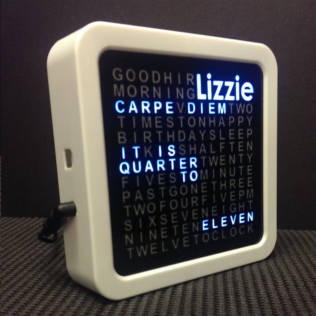
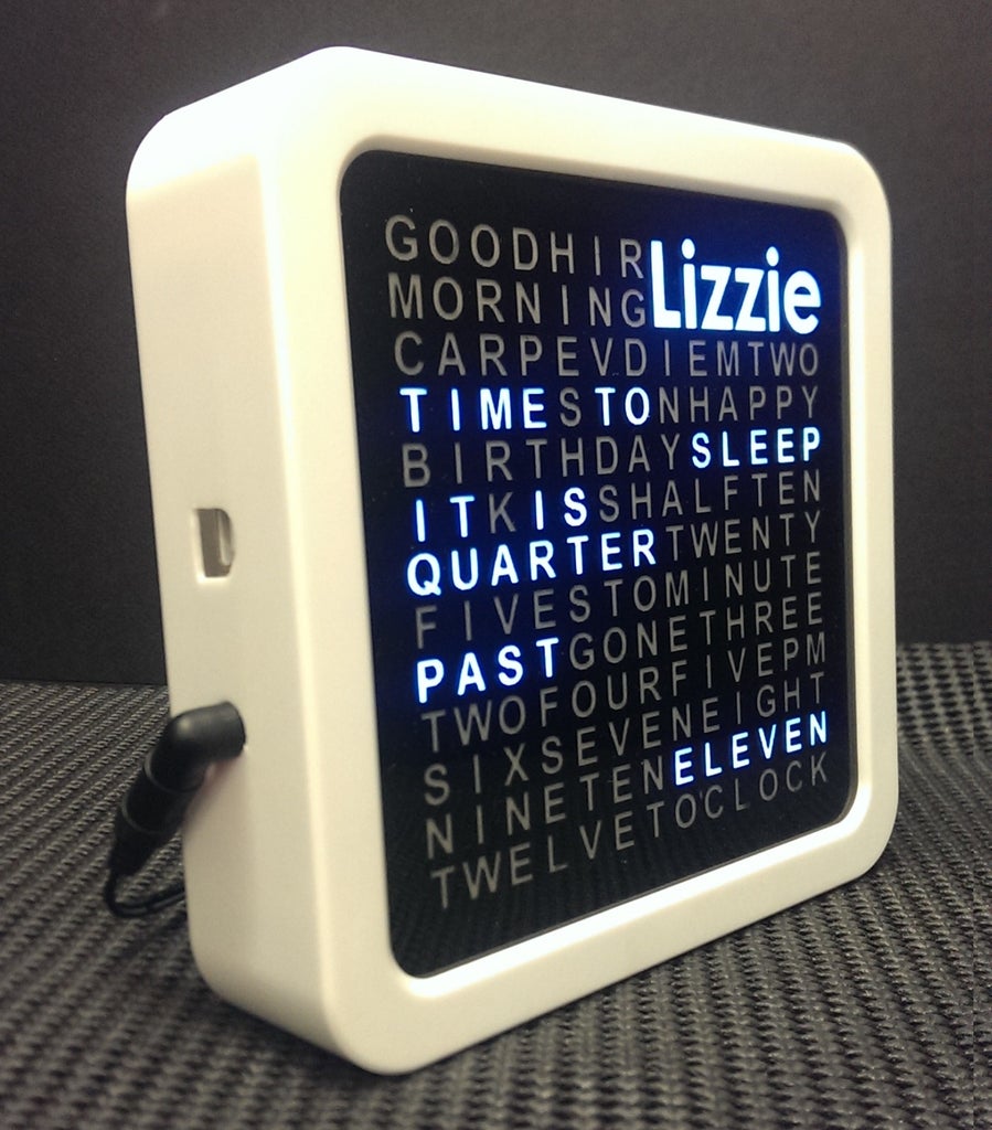
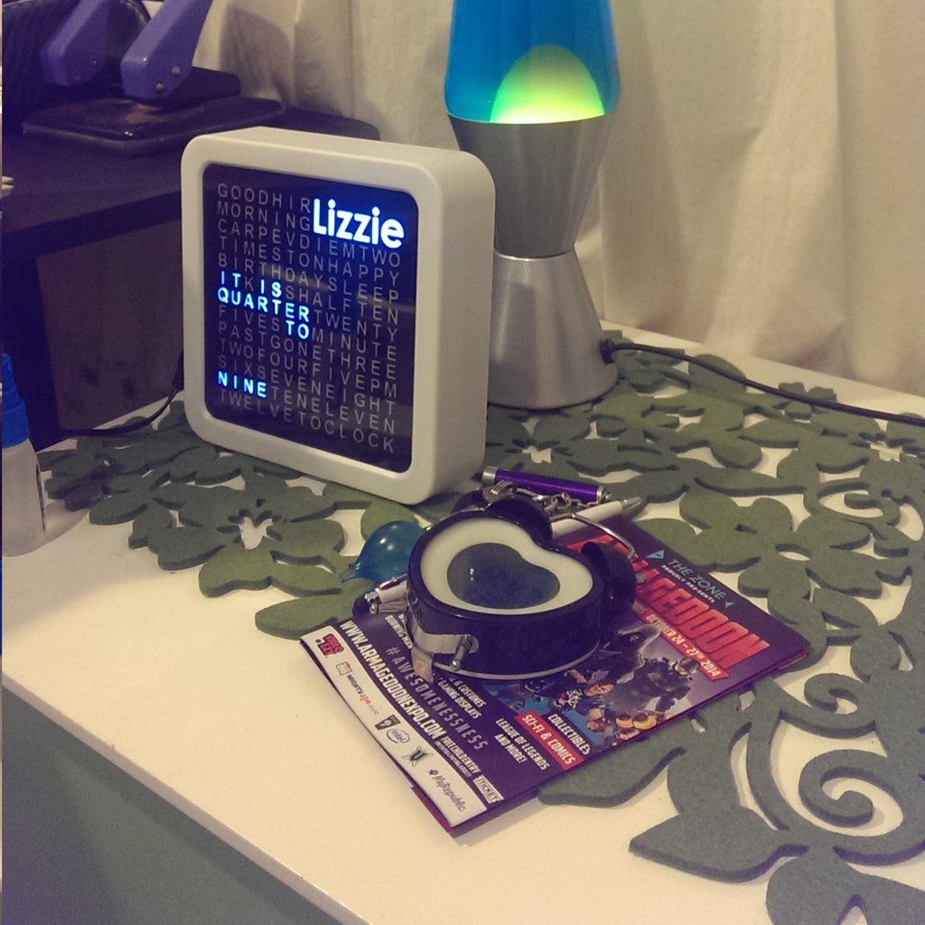
What’s different about this Word Clock is that it is small enough to sit on a bedside desk, displays the recipients name and has personalised messages that appear at different times ie. Happy Birthday, Carpe Diem, Good Morning or whatever you choose.
Great for people of all ages who enjoy something a little unique.
Please note: This a variation of the traditional word clock design. Credit must be given to the guys who came up with the original design. In particular these two instructables provided inspiration for this project
https://www.instructables.com/id/The-Word-Clock-Arduino-version/
Step 1: Gather Materials


The most important component for this project is a good enclosure. Most department stores will have a variety of low cost clocks that would be suitable. Look for funky looking clocks that have a glass front with a depth of at least 4cm.
Ideally you are looking for something that is a "shadow box" style enclosure which has a front aperture of at least 13cm x 13cm. The enclosure also needs to be able to be easily dismantled and the internal clock removed.
The electronic components are included in the list above. I tried to minimise the number of the components so went for an Arduino Mega to drive the LED array directly. See the circuit section for further details.
Step 2: Build Arduino Shield
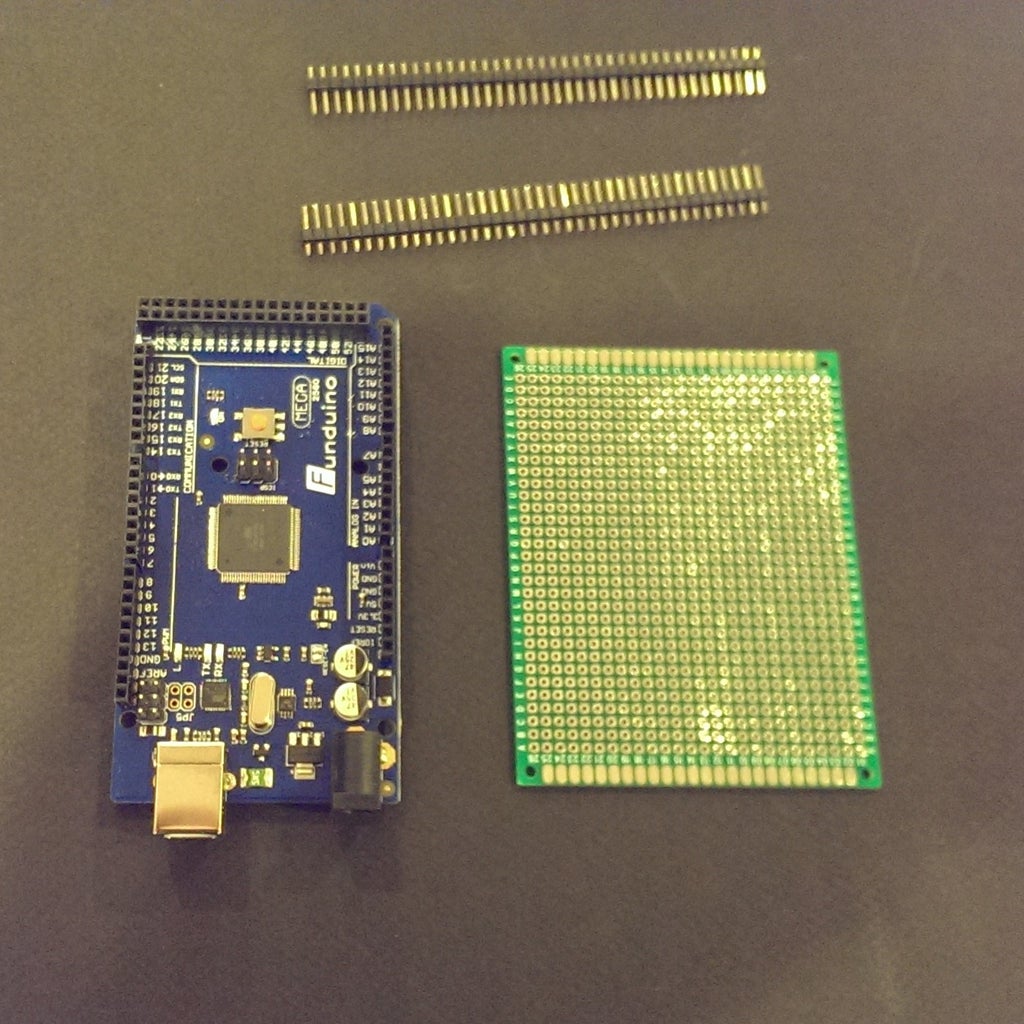


Arduino Shields are boards that can be plugged on top of the Arduino PCB extending its capabilities.
Building this simple shield enables you to connect the Arduino to the LED array, buttons, RTC and other components without having to solder directly to the board.
Cut the header pins to size and push into the Arduino board in the correct position as per the Circuit Diagram.
Then push the header pins into the shield to position the pins in the correct holes as per the picture above. Once you are sure they are in position solder the pins into the shield.
Remove the shield from the Arduino Board and Solder the 100 ohm resisters as per the circuit diagram and be careful to ensure that you have enough clearance when its plugged into the Arduino.
Step 3: Build the LED Display Board


1. Cardboard Cutout
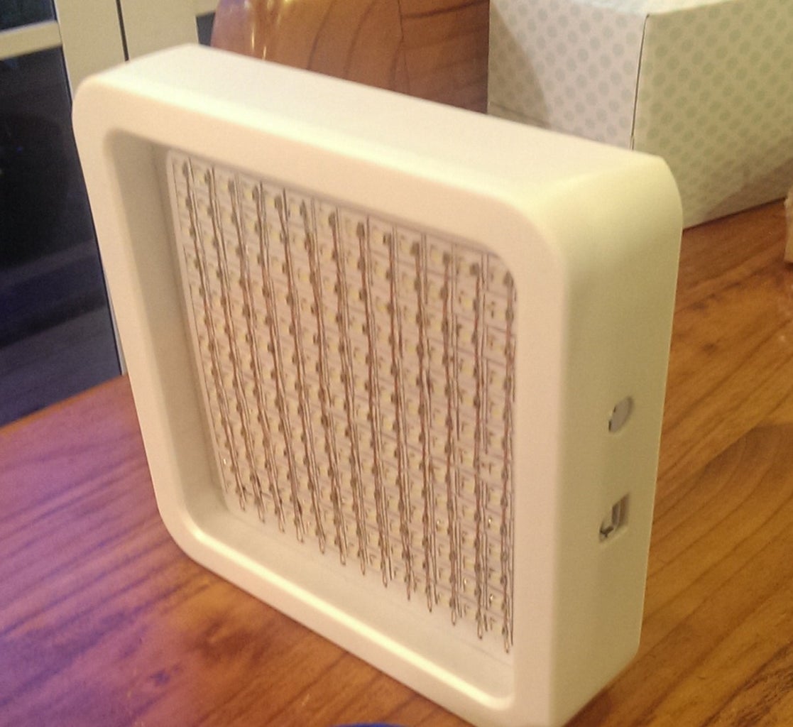
The Word Clock display is made up of an array of 13x13 LEDs that are mounted on a cardboard cutout that fits snuggly into the front of the Clock Case. It is best to use cardboard because it wont melt when you are soldering wires to the LEDs and its easy to work with.
Use the dimensions of the aperture of the Clock case to trace out the required shape and cut out a piece of 3-4mm thick cardboard.
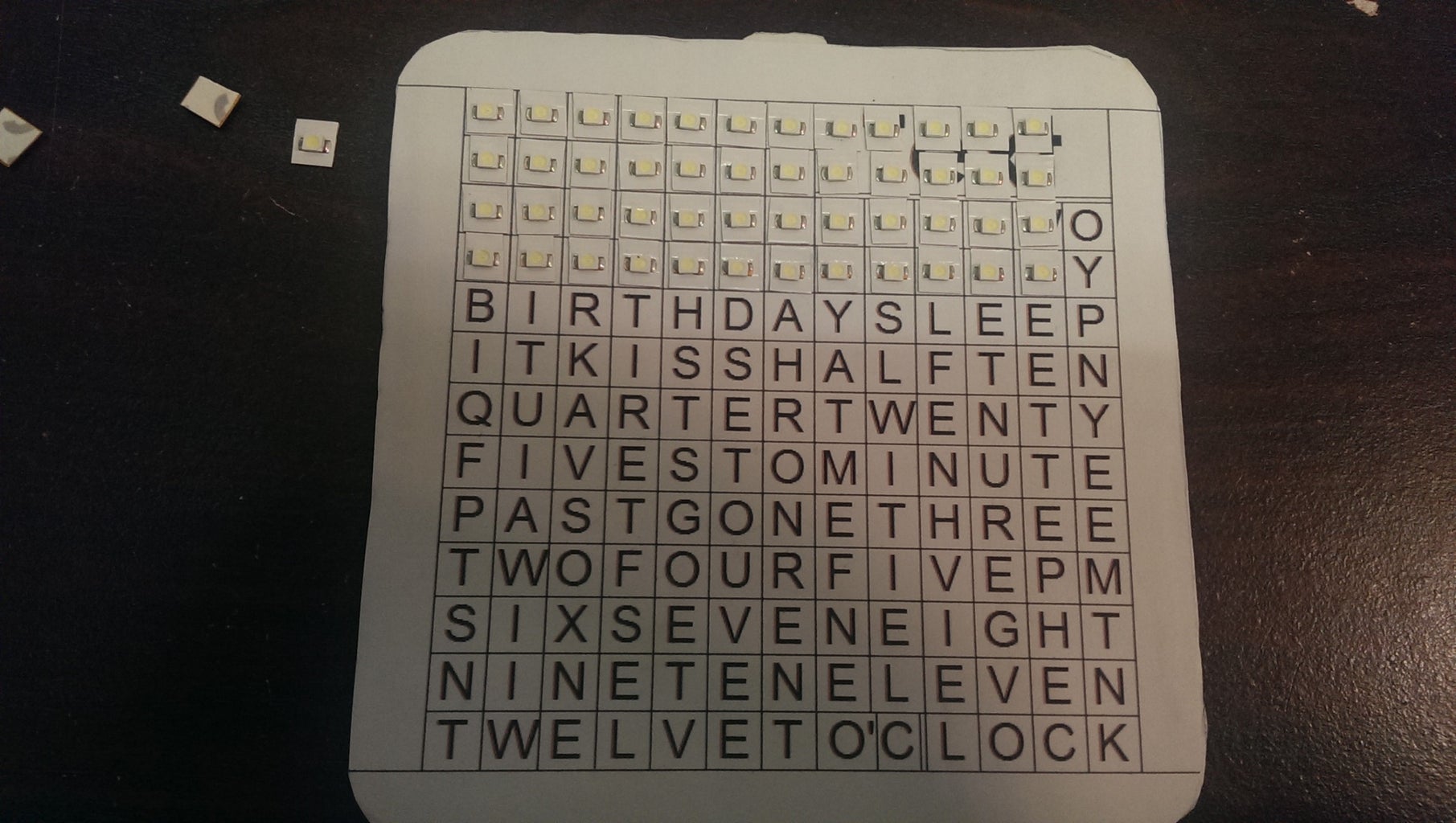
2. LED Grid
Use the enclosed template file to create 11cm x11cm grid to position the LEDs on the display board. Enclosed is a template that can be modified and printed out then glued onto the cardboard.
I used a free version of a draw program called LibreOffice Draw that you can download from here. LibreOffice The files can be modifed and resized using this tool. You can use the export feature to get different formats.
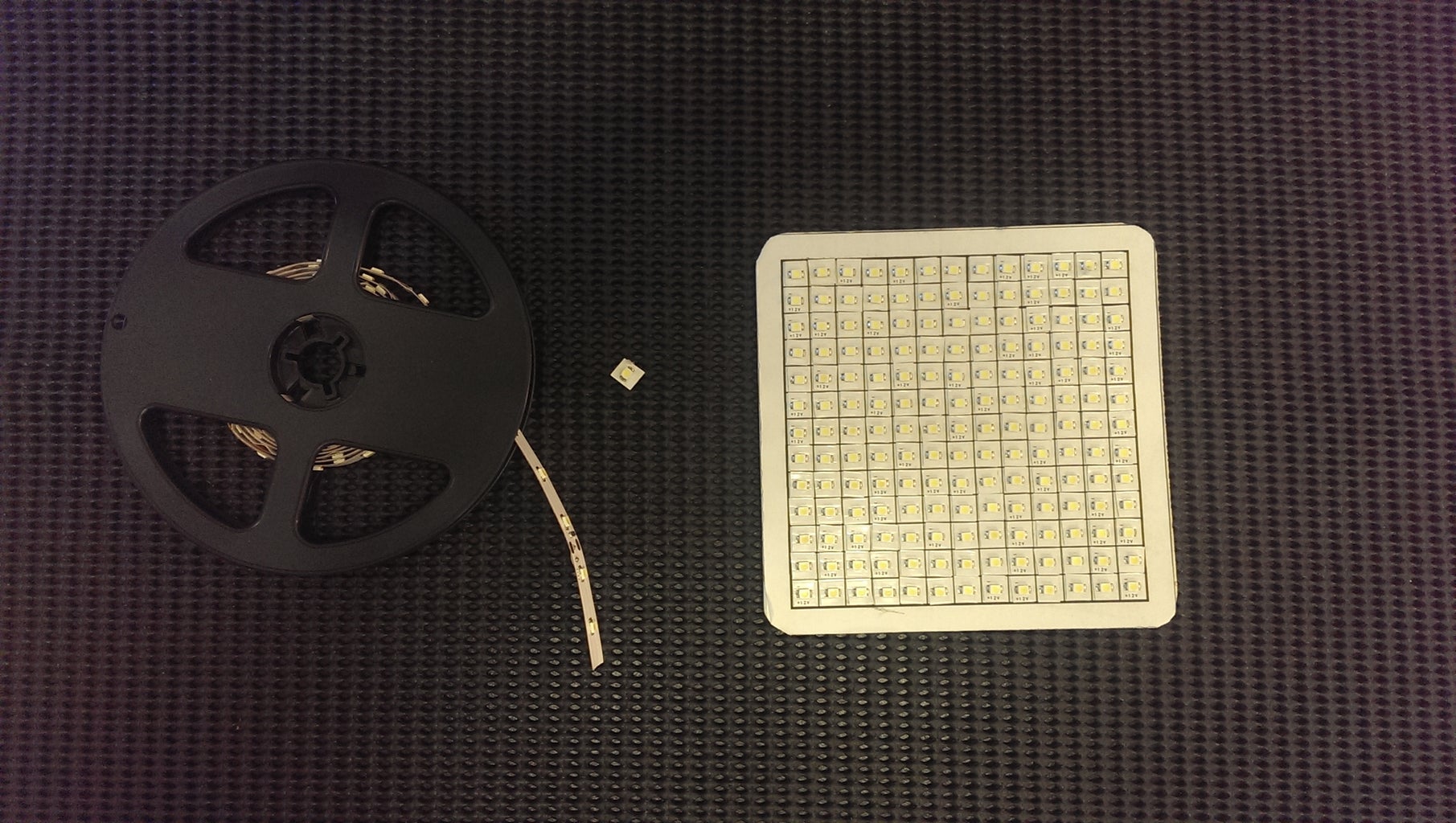
3. Mount the LEDs
In the example I used high intensity white surface mounted LEDs that I cut from a 3v LED strip. My advice is just use high intensity 3v Strip LEDs as they are easier to mount and don't require as much soldering.
(I recently did try 5mm LEDs and had a high LED failure rate and a lot of frustration with soldering so went back to strip LEDs)
The key point is that you join the Anode (+ve) side of each LED in each vertical column together on one side of the cardboard. Then pass the Cathode (-ve) through to the other side of the cardboard through a hole and join each row together on that side.
What you end up with is 13 Anode strips on the LED side vertically and 13 Cathode strips on the other side horizontally.
These are then connected to the Arduino Shield from the previous step as per the circuit diagram.
4. Test the LEDs
I recommend at this point testing all of the LEDs to ensure that there are no faulty devices/connections. To test use a 5v-9v DC power source and place a 2.2K ohm resister in line with the positive supply. Its important to do this to protect the LED from over current and burn out.
Connect the negative terminal to the LED Cathode and the positive terminal via the resister to the LED Anode of to test out. (Note ensure the Arduino Board is not connected when you do this). Make sure all the LEDs function and operate at the same brightness.
Attachments

Step 4: Build the Arduino Circuit


1. Overview
I tried to avoid the complexity and time required to have to put LED drivers in the circuit so for this reason have used an Arduino Mega to drive a 13x13 array of LEDs. The Arduino circuit and code reads the RTC time and then draws the display by turning on one LED at a time. It does this by addressing each LED systematically using X,Y coordinates. The LEDs are protected by 100 Ohm resistors and being that they are only activated individually this means the current is limited.
2. Planning
Position the components and carefully plan the mounting of the Arduino PCB, the Shield, Buttons and RTC PCB.
Ensure that the Arduino Board can be accessed externally for programming purposes as well as the external power socket. Do this by ensuring the Arduino power socket and serial port are close to the case edge. Th Arduino PCB will also require a screw fixing so that the power can be plugged in an removed without the Arduino PCB moving around.
3. Connecting up the components
Use hookup wire to connect the Arduino PCB, the Shield, Button PCB and RTC PCB as per the diagram. Play particular attention to the wires and position of the components to ensure they are fit snuggly and securely in the case.
Step 5: Test the Unit

Download Arduino IDE version 1.06 on your desktop machine
There are two additional libraries that need to be installed before setting the time and testing
(i) Arduino time library - see attached zip file
(ii) DS1307RTC library - see attached zip file
1. Set the time in the RTC
I used the following instructable code to set the current time on the RTC pcb.
https://www.instructables.com/id/Setting-the-DS1307-Real-Time-Clock-using-the-Seria/
2. Test the LED Array
Download the file"TechKiwi WC LED Array test.txt" and load to test the LED Array. When running each row of LEDs should light from top to bottom of the Clock.
3. Test Clock Functions without Dimmer and Time Set Buttons
Download the file"TechKiwi WC V5.7 TEST 2 code.txt" " and load to test the basic Word Clock functionality. When running the time should display however dimmer and time set functions do not work.
4. Final Test the Clock
Download the standard code provided on this page "TechKiwi WC Arduino Code.txt" and download into the Arduino. Once loaded the clock should be functioning with LEDs lit with the dimmer and time set functions working.
UPDATE: Ive included a new version of code that provides a nice animated effect, where the clock re-draws the text slowly every minute. Try it out and let me know what you think
Step 6: Build the Front Display


1. Build the Baffles
Measure the distance between the LED display board and the case glass. Cut 30 strips of A4 Black cardboard to the dimension of that distance.
2. Cut slots into the Baffles
Stack the strips of cardboard into a flat bundle and use tape to hold them together firmly.
Carefully mark the distance between each square on the top of the bundle. When marked correctly there should be 14 marks with the distance between them aligning to the LED panel.
Using a Band Saw or a Junior Hacksaw cut into the bundle 50% of the way through the mark as per the diagram.
3. Assemble the Baffles
Carefully dismantle the bundle and systematically assemble the Baffles as per the pictures. Trim the width of the baffles to fit into the box and ensure there is enough clearance on all sides. For the name TEXT cells remove the baffles as per the picture to ensure that they are not visible when illuminated behind the name TEXT.
4. Glue the Baffles onto tracing paper
The baffles are glued directly onto an A4 sheet of tracing paper over a stencil. Use five minute two part epoxy glue. Smear on baffle edges and hold in place over tracing paper until glue dries. This ensures the baffles are rigid and ensures that there is no light escaping between each cell when a LED lights.
5. Assemble the Word Clock Display
Using the template provided modify the text as required and get three black transparencies printed to the correct size. Get them printed in reverse so that when pushed against the glass the toner side is facing away from the glass. This gives a deeper black on the front display. I went to a local print shop and had this done in one of their colour laser printers which cost less than $4. My advice is to get about 9 copies in case you damage or make mistakes when cutting.
Cut the three sheets to fit the front panel of the box. trim the second and third layer progressively smaller so you can tape them down on top of each other once they are perfectly aligned.
Ensure you leave two sides open so that you can slide a square of tracing paper between the first and second layer of the transparencies.
Finally take the tracing paper that is glued to the baffles and trim to fit on top of the transparencies.
Carefully align the baffles on top of the transparencies tape into position making sure all letters have no obstructions or overlap. Hold up to the light to double check any issues and shake out any loose material.
.
Step 7: Final Testing


1. Set the custom birthday date
Use the Arduino tools to edit the provided code and change the date for the Birthday to align to the recipient or owner of the clock.
2. Test the clock transitions
You can use the tool mentioned previously to change the RTC date/time to check that all transitions occur.
Step 8: Adding an Alarm


There have been a number of requests to add an Alarm to the word clock. I have produced a new circuit and new code to accommodate this if you would like to build this version. The Alarm Time is saved once set and will not be impacted by power cuts. i.e Clock will remember Alarm time set if power is restored. The Alarm is produced by a Piezo Speaker.
1. Additional Parts
The additional parts required are
- 1 x Black Push Button for time/alarm set
- 1 x 10k Ohm pullup resistor
- 1 x Piezo Speaker
2. Time Set Operation
By pushing the Time Set Button once the clock will briefly display "TIME SET" mode and allow the increment and decrement of time using the plus and minus buttons. AM or PM is indicated in this mode by the word "MORNING" showing in this mode for AM.
To exit this mode,once the time is set, push the Time Set button once more.
3. Alarm Set Operation
Enter the Alarm Set Mode by pushing plus and minus buttons concurrently. This mode is indicated by "AL" text showing on the clock. To change the Alarm Time, use the plus and minus buttons.
In this mode if the Alarm is Armed when the word "SET" will show on the clock as well as the Alarm Time.
The Alarm can be Armed or Dis-armed in this mode. This is done by holding down the plus and minus buttons concurrently. When dis-armed the word "SET" will not show on the clock.
AM or PM is indicated in this mode by the word "MORNING" showing in this mode for AM.
To exit the Alarm Set Mode press the Black Set Button.
4. Disabling Alarm when it sounds
This can be done by pushing any of the three push buttons.

Second Prize in the
Tech Contest

Participated in the
Formlabs Contest

Participated in the
Microcontroller Contest


