

Introduction: Physical Pattern Lock


The pattern lock of Android device fascinates me. From the inspiration of Android pattern lock I made a physical pattern lock using IR sensors and Arduino microcontroller. You can use the lock where some sort of security is required such as your home or office.
No more tension about losing the keys!!!
The lock has following features:
- Contains 9 sensors and lots of patterns are possible
- Pattern change button to change the pattern anytime.
- LED Indication for wrong and right pattern
- Blocking facility for multiple wrong try
- Power saving mode
Demo Video
Step 1: Bill of Materials


Components
1. Photointerrupter (LTH-1550-01) (Seeedstudio.com)
2. ATmega328 with Arduino Optiboot (Sparkfun.com)
3. Mini Pushbutton Switch (Sparkfun.com)
4. Resistor 220 ohm (12 pcs)
5. Resistor 15k (10 pcs)
6. Resistor 1k (1 pcs)
7. Perfboard (3.5" x 2")
8. Acrylic Sheet (2" x 2")
9. Arduino (for programming the microcontroller)
10. General purpose transistor (2N2222 or equivalent- 1 pcs)
11. Lithium Ion Battery - 850mAh (Sparkfun.com)
12. LiPo Charger/Booster (Sparkfun.com)
13. Some jumper wires
Tools
1. Soldering Iron (Sparkfun.com)
2. Hot Glue Gun (Seeedstudio.com)
3. Diagonal Pliers (Seeedstudio.com)
Step 2: How It Works


The principle behind this pattern lock is very simple. I used 9 photointerrupters (Reflective Object Sensor) to implement the pattern. A photo interrupter integrates a infrared photodiode and an phototransistor in a single package. Photodiode emits a beam of infrared light and if any object places above the sensor's face the light is reflected back to the base of the phototransistor and works as a close switch. In my circuit each sensor is connected to a Arduino digital pin with a pull-up resistor. If a finger is placed in the sensor arduino reads it as logic zero as like a button press. Nine sensors are connected to nine different digital pin of the Arduino. When drawing a particular pattern you are actually pressing several buttons one after one. Arduino reads all the input and stores the result in an array according to the sequence you press. Then it is compared to the predefined sequence and if match then considered as a right pattern.
I included two momentary buttons into the circuit, one for updating the pattern and another for waking up the Arduino from the sleep mode. Avr deep sleep mode is implemented for saving the power as it is a battery power device. When no button is press or Arduino doesn't receive any pattern for five seconds then it goes to deep sleep mode. Wake up button is connected to the INT0 (interrupt zero) pin of the arduino and wake up from the deep sleep as you know an external interrupt can wake up arduino from sleep mode.
Two LEDs are connected to the circuit for indicating the actions and the results (given pattern is right or wrong or want to change the pattern). For the right pattern green led blinks for three times and for any wrong pattern red led blinks three times.
For updating the pattern you first need to enter the right pattern and then need to press the update button. Glowing red led means it is ready to take new pattern. After giving a pattern green led blinks two times for successful update.
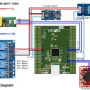
Schematic for the complete system, pin-out for the sensors and the datasheet are attached in the step.


Step 3: Soldering the Sensors


In a 2 inch x 3.5 inch perfboard place all 9 sensors as like attached photo and solder all with a soldering iron. The gap between each sensor should be identical. You should also place the sensors in the board in such a way that all are identically place considering the pin-out of the sensors to make the soldering easier. Connect a 220 ohm current limiting resistor to every photo diode to keep it safe from burning out. The value of the resistor may be slightly different. Follow the device datasheet for details. A 15k pull-up resistor must be connected to the collector pin of the photo transistor. Changing the value may change the sensitivity of the sensor. I found good performance for 15k but higher value should also work. For completing all the connection you may required some jumper connection. I used all jumper wires at the bottom side to keep it clean at the top as it will be the visible part.
Are you new in soldering? You may follow the link below:
- Sparkfun: How to Solder: Through-Hole Soldering
- Instructables: How to Solder
Step 4: Soldering the Microcontroller


For soldering the Arduino microcontroller to the circuit board I used 28 pin IC base. Using an IC base without directly soldering an IC to the perfboard has some advantages and you can easily remove or replace an IC without desoldering. Connect a 16 MHz crystal with two 22pf capacitor. Capacitors provide batter stability for the crystal and microcontroller.
I used a 2N2222 general purpose transistor to drive all the photodiodes. The base of the transistor is connected to the digital pin #3 of the arduino. Driving photodiodes with transistor and microcontroller gives me the opportunity to turn of the sensors when arduino is in sleep mode and reduce the power consumption in a great extent. If you connect all the sensors directly to the power supply then it is not possible.
So, solder a transistor to the board in a convenient location. Don't forget to add a 1k resistor to the base of the transistor.
Step 5: Soldering Buttons & LEDs


Now, connect two momentary buttons, one green LED and one red LED to the board according the circuit diagram. Don't forget to connect current limiting resistor with the leds. Always try to put any button in a easy accessible place of a circuit board. I put both button at the bottom edge of the circuit board. No pull up resistor is required with the button switch as internal pull up resistor is enabled in the arduino sketch. You may require several jumper connections to complete the circuit. I suggest to connect all jumper wires to the bottom side of the board to keep top side good looking.
Step 6: Attaching Acrylic Sheet


Take a thin 2" x 2" transparent acrylic sheet and place it to the top of the sensor's face. Place it in such a way that, it perfectly aligns with the circuit board. Then use hot glue around the sides to fix the acrylic sheet with the circuit board. Follow the photos attached above. The acrylic board should be thin enough otherwise it may effect the sensors output. Use as thin as you get, mine is 3mm thick and working perfectly.
Step 7: Attaching the Lock (Funny Thing)


This is the funnest part of the project. I attached a lock at the back side of the circuit board using hot glue. Use enough glue to keep the lock separate from the circuit board otherwise it can short the pads. Then I attached the key of the lock with a 9g micro servo. After that I fixed the servo in the circuit board. I kept all perfectly aligned when glued with the board.
For the right pattern the servo rotates the key at 45 degree to open the lock. You see here both lock and key are attached with the circuit board with glue. It is a funny approach and only for demonstration. But this may be done if you can enclose lock, key and the servo within a hard and durable box. You can also implement the pattern circuit in any other lock in a creative way.
Step 8: Uploading Program


The program for the microcontroller was developed in Arduino environment. I used Arduino UNO for uploading the program to the microcontroller and then I remove the IC from the UNO board and placed the microcontroller to the circuit board. For storing the updated pattern I used internal EEPROM of the Arduino microcontroller. The simple demo sketch is attached at the bottom of the step.
#include
//1-26, 4-27, 7-28, 2-19, 3-16, 5-23, 6-17, 8-18, 9-15 (ic-pin)
//1-17, 2-13, 3-10, 4-18, 5-14, 6-11, 7-19, 8-12, 9-9 (Arduino)
 //EEPROM.write(address, value)
  //EEPROM.update(i, i);
  //value = EEPROM.read(a);
#include
Servo myservo;  // create servo object to control a servo
const byte one = 17;
const byte two = 13;
const byte three = 10;
const byte four = 18;
const byte five = 14;
const byte six = 11;
const byte seven = 19;
const byte eight = 12;
const byte nine = 9;

int set_pattern[9] = {1,2,3,5,7,8,9}; //Z pattern
int try_pattern[9];
int pattern_number;
int try_number = 0;

void setup() {
  // put your setup code here, to run once:
  Serial.begin(9600);
  myservo.attach(3);  // attaches the servo on pin 9 to the servo object
  myservo.write(0);
  pinMode(one, INPUT_PULLUP);
  pinMode(two, INPUT_PULLUP);
  pinMode(three, INPUT_PULLUP);
  pinMode(four, INPUT_PULLUP);
  pinMode(five, INPUT_PULLUP);
  pinMode(six, INPUT_PULLUP);
  pinMode(seven, INPUT_PULLUP);
  pinMode(eight, INPUT_PULLUP);
  pinMode(nine, INPUT_PULLUP);
  pinMode(15, OUTPUT);
  pinMode(16, OUTPUT);
  pinMode(7, INPUT_PULLUP);
  pinMode(2, INPUT_PULLUP);
}

long previous_millis = millis();

void loop() {
  // put your main code here, to run repeatedly:
  // any button is or within 2s, it is in a trial
  if(button_read() || ((millis() - previous_millis) < 3000)){
  if(button_read()>0){
    if(try_number>0){
      if(button_read() != try_pattern[try_number-1]){
        try_pattern[try_number] = button_read();
        try_number++;
         }
       }
    else{
      try_pattern[try_number] = button_read();
      try_number++;
       }
    previous_millis = millis();
     }
  }

  if(try_number>0 && !button_read() && ((millis() - previous_millis) > 3000)){
    if (array_cmp(set_pattern, try_pattern, try_number) == true){
           // correct pattern
      //  if(!button_read){ //unlock
           Serial.println("Correct Pattern");
           digitalWrite(15, HIGH);
           delay(500);
           digitalWrite(15, LOW);
           delay(300);
           digitalWrite(15, HIGH);
           delay(500);
           digitalWrite(15, LOW);
           delay(300);
           digitalWrite(15, HIGH);
           delay(500);
           digitalWrite(15, LOW);
           delay(300);
           open_lock();

    }else{
           // wrong pattern
           Serial.println("Wrong Pattern");
           digitalWrite(16, HIGH);
           delay(500);
           digitalWrite(16, LOW);
           delay(300);
           digitalWrite(16, HIGH);
           delay(500);
           digitalWrite(16, LOW);
           delay(300);
           digitalWrite(16, HIGH);
           delay(500);
           digitalWrite(16, LOW);
           delay(300);
    }
   array_nul(try_pattern,  try_number);
   try_number = 0;
  }

  if(!button_read() && ((millis() - previous_millis) > 5000)){
   //May sleep here
  }
 delay(100);
}

int button_read(){
  if(!digitalRead(one))
    { Serial.println("1");
      return 1;}
  else if(!digitalRead(two))
    { Serial.println("2");
      return 2;}
  else if(!digitalRead(three))
    { Serial.println("3");
      return 3;}
  else if(!digitalRead(four))
    { Serial.println("4");
      return 4;}
  else if(!digitalRead(five))
    { Serial.println("5");
      return 5;}
  else if(!digitalRead(six))
    { Serial.println("6");
      return 6;}
  else if(!digitalRead(seven))
    { Serial.println("7");
      return 7;}
  else if(!digitalRead(eight))
    { Serial.println("8");
      return 8;}
  else if(!digitalRead(nine))
    { Serial.println("9");
      return 9;}
  else {
    Serial.println("0");
    return 0;}
}

boolean array_cmp(int *a, int *b, int len){
     int i;
     // test each element to be the same. if not, return false
     for (i=0;i
Attachments
Step 9: Testing


As you uploaded the program to the IC, now you are ready to power up the circuit and test your creation. A 3.7V li-ion battery is capable to drive the circuit with servo motor. Though I found it working, it will be good if you attach a 5 V boost converter module to the battery and then supply the power to the circuit. It will increase the stability of the system. You should also attach a battery management circuit for charging the battery. After powering the circuit test it using 'Z' pattern as it is defined in the code.
Arduino deep sleep is use to save the power. A single charging can drive the system more than five month but it depends on your use.

Participated in the
Sensors Contest 2017

Participated in the
Microcontroller Contest 2017


