Introduction: Pixel Drop Ceiling
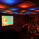
In our living room we have a small patch of drop ceiling right in the middle of the room, basically a giant piece of duct tape to cover up bad carpentry. It was constantly getting water damage from what looks like a giant hole in the ceiling above the drop tiles. After roughly a year of living in the house I decided to take action. The Pixel Drop Ceiling was born.
The Pixel Drop Ceiling is a Bluetooth, Arduino powered, Computer controlled, RGB, Drop Ceiling. The perks of being controlled by the computer are that the whole system is music controlled and its easy to change and create your own patterns with little software know-how. You can then change these patterns on the fly without having to upload new software to the Arduino, allowing you to create your own "show" in essence.
Step 1: Materials
- Stratford Translucent Ceiling Tiles
- Black Paint
- Arduino Uno R3
- Arduino Proto Board
- HC-06 Bluetooth Transceiver
- 30mm WS2801 LED's
- 12V 5A Power source
- 2k resistor
- 1k resistor
- 2.1mm Power Jack
When choosing Ceiling Tiles you don't have to go with the Stratford that's simply what I chose, just make sure that no matter what design of tile you get that you buy the translucent tiles, NOT the white tiles. The Translucent tiles are made purposely to put lighting fixtures above and they look amazing when you do so.
Step 2: The Circuit
The circuity is fairly simple, just make sure that you power the LED's externally using the 12V power source and you power the HC-06 using the 5V pin on the Arduino. The circuit is exactly the same as my previous Instructable the Bluetooth RGB Shelf Lighting, the only difference between the two is the firmware on the Arduino itself which I will explain in the next step. When wiring to the LED's its normally a good idea to make some sort of easy disconnect, you can see what I used in the pictures above.
Step 3: Ceiling Assembly
These ceiling tiles are very flexible so it makes for a very easy installation. For the half sized tiles on each side of the drop ceiling we simply held down the tiles with a straight edge and cut it with scissors, the lip around the edge gives you a little bit of tolerance for any mess up. As for the wires ran to the ceiling for the LED's I was "lucky" and had a giant hole in my ceiling that conveniently led straight to my room up stairs. The original drop ceiling grid was white but painting it black gave it much more of a "Grid" look, which in turn made for better looking separation between pixels.
In order to mount the WS2801's I took the easy way out and simply used double sided mounting tape to stick them to the ceiling along with duct tape to hold up the wires, I wasn't too worried about harming the existing ceiling, because of the already present "Giant hole". When you mount them too the ceiling put them in some time of serpentine pattern. The matrix software will then compensate for what pattern you have them in and change the patterns as needed.
Step 4: Arduino Software
The software for the Arduino is quite simple, it receives incoming pixel data and lights the LED's accordingly. The guys over at SolderLab were kind enough to offer their sketch for the Uno and Mega Arduino boards. This sketch works with the Glediator and J!nx LED Matrix software, I will explain more in the next step. When using the Arduino Uno software at 500,000 BAUD you are limited to controlling 512 LED's, if you were to go with the Mega version the firmware is run at 1,000,000 BAUD allowing you to handle roughly 1024 LED's. Links to both the Uno and Mega Sketches are below.
SolderLab's Sketches (You will have to change the BAUD as shown below if you use these!)
- Arduino Uno WS2801
- Arduino Mega WS2801
- Attached is my modified code w/ BAUD changes
In order to use this software with Bluetooth integration a little work is required. The HC-06 cannot run at 500,000 BAUD, to fix this you need to modify the default BAUD rate on the Bluetooth transceiver as well as in the Arduino code. We'll mess with the defaults on the HC-06 in the next step. I've already made the necessary changes to Arduino code posted below, in case you don't want to use Bluetooth serial or your starting fresh with Glediator's sketch what you need to do is change this:
~~~~~~~~~~~~~~~~~~~~~~~~~~
//UART Initialization
UCSR0A |= (1<<U2X0);
UCSR0B |= (1<<RXEN0) | (1<<TXEN0) | (1<<RXCIE0);
UCSR0C |= (1<<UCSZ01) | (1<<UCSZ00);
UBRR0H = 0;
// UBRR0L = 3; //Baud Rate 0.5 MBit --> 0% Error at 16MHz :-) <strong> <--Comment Out This Line</strong>
UBRR0L = 16; <strong><----- Add in this one</strong>
~~~~~~~~~~~~~~~~~~~~~~~~
What this does is it drops the incoming BAUD rate from 500,000 to 115,200, the max BAUD rate of the HC-06. Make sure that you change the header to your number of pixels as well, as seen below:
#define Num_Pixels 28
Compile and upload!
Attachments
Step 5: Bluetooth Integration
The whole reason for integrating Bluetooth is so you don't need to run any wires from the ceiling to your computer, allowing you to control the system from anywhere. You do have to have either Bluetooth already in your computer or else you'll have to go out and buy a Bluetooth dongle, they aren't that expensive, posted below is a link to the one I use:
Before you go any further you have to change the default setting on the HC-06, the default BAUD needs to be changed from 9,600 to 115,200. This is because you will be streaming pixel data to the Arduino at roughly 24fps, therefore the BAUD needs to be raised to compensate for all of the data. 115,200 is the max BAUD rate for these transceivers. I will not go into how exactly to change the defaults in this post because there is already an Instructable that does a great job of showing you how.
Modify The HC-05 Bluetooth Module Defaults Using AT Commands
For instruction on how to set up your Bluetooth COM port on your computer, follow the comments on the pictures above, these were taken on x64 Windows 7.
Step 6: LED Matrix Control
For the longest time I was attempting to write my own software to control the ceiling and table alike. After lots of struggle I stumbled across these two different programs, needless to say they simplified the process ten fold. Both programs do the same thing essentially, they generate different patterns in a specified matrix size and output the data to specified devices. Both also operate with SolderLab's WS2801 sketch that I previously provided. I've messed around with both of them quite a bit and where I settled was with Jinx, Glediator is also great software but a little more difficult when it comes to outputting to two different devices (what you'll see me doing in my final product video in the next step). Jinx also allows you to write your own code for patterns and I found it to be a little more user friendly.
Here are the links to both websites, they provide detailed instructions on how to use their software:
Glediator
Jinx
In the pictures above I gave a brief explanation on how to setup Jinx. You simply add in your output device, in this case the ceiling, then patch the device, this means that you compensate for the way you serpentine your LED's and their input method of color data. Once you have that set, click on "Setup" then select "Start Output" and you should see your ceiling spring to life!
This software has tons of features including music control so you can create an endless amount of designs. The best way to get to know the software is just to play around with it.
Step 7: The Final Product
Here is a short video I put together displaying what the ceiling is really capable of, the table you see in the video is also being controlled by the LED matrix software allowing me to run them together. Hopefully when I have more time I will create another Instructable on how to do this yourself.
Hope you guys enjoyed! and i'd love to hear your feedback!
I've also entered this into a couple of Instructable's contests, I would really appreciate your vote!!
Thanks!

Grand Prize in the
Home Technology Contest

Participated in the
Remote Control Contest

Participated in the
squeeze more awesome out of summer contest


