

Introduction: Portable Game Emulator


This project started several years ago when I first saw Raspberry Pi embedded into a Gameboy case. Sadly my electronics skills were nowhere near the level required to assemble it. Now that my skills are finally up to par for the challenge the whole thing just didn't feel practical enough.
First thing that I had issues with is that the whole thing wasn't modular at all and any fault that might occur within the unit would take at least some soldering to fix. Second thing is that when I picked up my old Gameboy before ordering the case, it felt too small for everything I wanted to put in it.
Thus I decided to make a custom enclosure, and being how I don't own a CNC or 3D printer it got made with hand tools.
I got a lot of the inspiration from PiGRRL2 and numerous projects here on Instructables, as well as Ben Heck's Show on youtube.
Step 1: Parts and Tools List

- Raspberry Pi 2 model B and SD micro memory card
- SNES USB controller (cheap chinese)
- PiTFT Plus 320x240 2.8" TFT + Resistive Touchscreen
- RPi PowerPack V1.1 3800mAh (cheap chinese power supply for the Pi)
- USB charging cable
- 2x Red momentary push button switch, non latching (cheap chinese)
- Black momentary push button switch, latching
- 3.5 mm audio jack and plug
- Dupont jumper wire female pin connector + Housing (male pins were scavanged)
- several old USB cables (for wires)
- various screws, nuts and washers
- 7mm plywood
- 1mm thick plastic (got mine off an ice-cream container)
- wood glue
- heat shrink tubing
- ruler and pencil
- hand saw
- jigsaw
- scalpel
- pliers
- sandpaper
- rasp (various types)
- rotary tool (and few bits)
- drill
- clamps
- soldering iron, helping hands and rosin core
- tweezers
- wood paint and brush
- 1A USB power adapter and charging cable, HDMI cable and monitor, RJ13 cable, internet connection, SD card adapter and keyboard for setup of the system
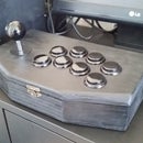
Step 2: Controller and Button Enclosure


Started with dismantling the SNES controller and marking the holes on the front side of my case. I had no intentions on building the controller circuit board from scratch since the SNES one was perfectly good and only required adapting my enclosure to it. I cut out most of the button holes with the scalpel after drilling through.
Step 3: Thinning


I continued to thin out the wood until it felt that the button clicks felt somewhat proper. It took about half an hour until I was satisfied with the feel of the buttons.
Step 4: Controller Circuit Board


Since the bottom of the rubber pad is 1mm thick I put a piece of same thickness plastic around it. That way when putting the circuit board on it, it would sit the same as in it's original case. A screw is used to fasten the circuit board into place so it can be taken apart easily later.
Step 5: Better Securement


I wasn't quite happy with the stability of the circuit board so I made two wooden clamps and screwed them down. I also installed two laptop speakers but those were later discarded; will explain this part later. I also added a rather large washer to hold down the USB cable.
Step 6: Layers


Then I proceeded to build an extra layer on the top of the case and started building the bottom part. A lot of wood glue was used. I also tried to make the bottom as comfortable to hold as possible, therefore giving it a somewhat curved design.
Step 7: Extra Pins on the Circuit Board


I desoldered the original shoulder buttons and instead of soldering the wired directly I soldered 2 male pins on both ends so I could connect it with dupont female pins. The screen also arrived at this point so I made a hole for it in the front of the case.
Step 8: Too Long USB


The USB cable on the controller was too long so I shortened it. Afterwards I isolated the wires with heat shrink tubing to make sure there would be not shorts.
Step 9: Installing the Battery


Next came the installation of the battery. I'm gonna go on and say that I have somewhat of a love hate relationship with this particular "power supply".
I love it for it's price (10€) and simplicity and I hate it for the terrible craftsmanship. The on/off switch broke after 7 uses and charging port broke loose after few uses. If you opt for this one just remove the on/off switch right away (leaving the unit in a constant on state) and add solder to the mini USB's pegs.
I put the spacers onto the back, put the "power supply" on them and soldered on two wires onto the USB port. I decided not to remove the female jacks but simply walled them in instead.
Step 10: Inputs and Outputs


Combining all the components was next. I pulled the wires from 3.5 mm plug, made on/off switch and cut off the end of the charging cable. I put Dupont pins on all the of the wire ends (except audio ones), connected everything and tested it. I also secured the Raspberry to the back.
Step 11: Cover Modification


As the power input wire was sticking out of the case I made a lid for it so it would hold it in place and also apply a bit of pressure so there would be no chance of it unplugging. Of course, I could've made the case a bit bigger but at this point I really didn't want to remake the whole case again.
Step 12: OS Setup


At this point I installed the Retropie OS on the Pi and set up the screen. I won't detail the process here as it has been covered in a lot other places. However here are the links with detailed instructions:
Step 13: Shoulder Buttons


I used a scalpel to cut out the letters for the buttons on the front. Since my push button switches finally arrived I drilled two holes in the back for them and installed them. After some testing I figured I needed to put some extra material on the back which would prevent the buttons from being pushed when the unit was left on a flat surface. I also added extra wood next to the power button so it wouldn't get accidentally turned on.
I drilled pilot holes and added 3 screws in the back which combined two plates together.
Step 14: Some Testing


Since the amplifier had not arrived yet I began play testing the unit. Also I sanded the whole case and prepared it for painting.
Step 15: Sound Output


When the audio amplifier finally arrived I decided to completely scrape the idea and installed the 3.5 mm audio jack to the bottom of the device.
There were a few reasons for not installing the amp and speakers, which I'll elaborate. One of them being Pi 2 has a utterly horrible audio quality coming from the 3.5 mm jack. The constant white noise "hiss" can be dealt with by adding disable_audio_dither=1 to config.txt
Read more about that in this board discussion.
Step 16: The Fails


The audio amp I opted for was PAM8403 chip class D. It was quite easy to install, and I connected it to the common ground. I also added a 470uF capacitor to it since it was on the battery. I secured it to the front panel with a piece of plexy and screws. It played the sound but several other problems occurred.
It kept giving out high frequency noise which came from the battery. After hooking it to a different power source the high frequency noise was gone. There were other solutions to this problem like: making a low-pass audio filter or a RC filter circuit. I opted for neither for the third reason: the PAM8403 draws an obscure amount of power on boot which causes the Pi to end with very little current to work with.
Simple solution would be to order an amp from Adafruit, either MAX98306 for stereo or PAM8302A for mono. Both of these have audio filters built in and draw far milliamps from the battery.
First screen I decided for was a cheap chinese (10€) knockoff the Waveshare32 unit. It was a 3.2 inch 320x240 LCD and was relatively easy to install and setup. However it stopped working after 2 days, and even though the seller sent me a replacement unit I decided not to use it since it took over a month for the replacement to arrive (and my wife bought me the PiTFT).
However, I've read more than several good reviews about the said screen and I might have just been unlucky with the first one that I got. If you decide on the said screen, installation instructions for it are here.
Step 17: Finally Done


After applying paint I wasn't satisfied with the blue/green button combo on the front so I changed it for the yellow/red. Finally I was happy with it and thus the project was complete. The wear of the paint on the corners and the D pad is after 1 month of playing; I used water based acrylic paint without base or finish overcoat to get the worn-out look. This is intentional.
Battery lasts for 6 hours of continuous playing; this was thoroughly tested.
Step 18: The Pouch


This was made with polyester fabric sewn around bubblewrap, and quick-release buckle added. In this case I'll just let pictures do the explaining.

Participated in the
Epilog Contest 8


