

Introduction: Portable Solar Powered Air Filter


The objective of this Instructable is to create a solar powered air filter. Since I'm using a Voltaic System 6 Watt Solar Charger Kit, the device is very portable and can also be used to simply increase air flow, for example in a hot tent.
Have you ever looked at a device and decide something wasn't quite right?
For me air filters are like that. Much like the proverbial electric fan used to power a sailboat, air filters trap pollutants in one location, but, follow the cord to the outlet, and one might wonder how efficiently we're using energy. What if the sun powered the air filter?! Using the Voltaic system solar charging system. we can power a fan to push air through a filter.
Tools required:
- Pliers
- Knife or scissors
- Electrical Tape
- Wire strippers
Equipment Required:
- 6 Watt Solar Charger Kit http://www.voltaicsystems.com/6wattkit.php
- Choice of enclosure
- USB cable
- Filter / filter material
- Computer case fan
- Velcro straps
Step 1: The Chain of Energy Inputs

The Voltaic 6 Watt Solar Charger Kit comes with a 8.7 x 6.9 x 0.2 in waterproof solar panel. The most common use for this device is to charge cell phones and tablets. Not directly but by charging a battery pack which can then be used to charge the mobile device. Voltaic does supply a micro usb adapter which allows some Android devices to be charged directly from the solar panel. For this project I tried using the panel to drive my fan however, even when I used a fan with no LEDs the fan wouldn't function (it has been cloudy here too so I've been using artificial light which probably doesn't help) So I decided to stick with the battery pack to drive the filter fan.
Okay the plan is simple. The Voltaic Solar panel has a standard USB port, the supplied cable fits into the solar panel on one end and into the micro USB port on the battery pack. Once the battery pack is charged, the USB cable can be plugged into the battery pack output port (standard USB) and then into the device to be charged. There are both mini and micro USB adapters for the charging cable
To power my filter fan, I took a standard USB cable and used one end as is for the USB port of the battery pack. I cut and stripped the red and black wires from the cable These wires are the outer two pins of the USB connector and they connect to the fan.
Step 2: Fabricating the Fan Enclosure.


Next we need an enclosure for the fan. Hey look at that take home container...
that looks like it might work... Let's make some strategic cuts with a utility knife, using the fan as a guide to mark the area to cut.
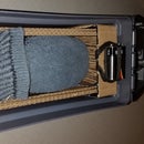
I covered the fan intake with a coffee filter. I just used some tape to hold the filter in place. Then punched holes at the four mounting holes. Because it was on the intake , the filter was being drawn in enough to be rubbed by the moving fan blade. To correct this, I added a folded wedge of an index card to give it some more spacing/strength. I mounted the fan on some rubber fasteners, to reduce vibration noise.
There was spare room so a particulate trap might both help catch additional material and give visual feedback to the effectiveness / seal of the filter. The trap is made from a folded index card, that will serve as a base for some petroleum jelly. (to be applied when filter material is replaced) I saw this way back when.... roll 20 memory - knowledge arcane! If memory serves, it was presented as a way tho show the difference in air quality for places with smoking and without. It relied on natural air flow. We are going to take it to the next level by blowing air across the petroleum jelly particulate trap. I chose to place the opaque side of the enclosure up to keep the sun off the card. I was excited to set this up in my window to see how well this gadget worked.
My hope was to catch the bigger stuff right away, without restricting airflow too much. Once fitted, and running, I found the filter blocked way too much of the airflow, and easily became torn. So time to watch for sales on air filters. I know that buying and using a Hepa filter would provide superior results. I will switch to one later.
Step 3: Adjusting the Panel - Extra Credit


As a side trip, we spent some time on finding an automated way of aligning the solar panel.
The idea was: suppose you are camping and want to charge your battery or run your tent fan while off hiking, perhaps a servo and some light sensors could tilt the solar panel to follow the sun for optimal charging....perhaps this is not practical for one solar panel, but we thought it would be a fun experiment and surely useful for a rack of solar panels.
In true makerspace style, we happened to find a junked automatic side-view car mirror. The mirror contained a motor which provides 3 degrees of rotation controlled by 3 wires. We mounted the motor on what was handy, an old popcorn tin for the base and a ceiling fan blade as a base to attach the solar panel. Testing this out by providing 12V power to pairs of wires, I learned selecting 1 pair would make the motor tilt to the right and another pair would make the motor tilt to the left. Reversing the polarity of power to the pairs had the opposite effect. For prototyping proposes I decided to use only one pairing. to tilt the motor left and right.
To switch the polarity of power across the motor, I needed an H bridge . Wikipedia discusses the function in the following article : http://en.wikipedia.org/wiki/H_bridge The basic idea is that either terminal can be switched to power or ground, but that the switching needs to be selected such that a short is not created. One can switch with either a switch manipulated manually, or by a relay which would could be signaled by a micro-controller.
I first built an H bridge with solid state relays. This choice was driven by the hope for simpler signalling from the controller. Unfortunately, in this configuration once switched on they tended to stay on until power was removed. So we redid the H bridge with mechanical relays. The mechanical relays worked better and provided the benefit of isolating the control and load circuits. However, the control inputs required more more current than could be driven by some micro-controllers. The following article describes one way to connect an Arduino to a relay: http://makezine.com/2009/02/02/connecting-a-relay...
Some thoughts left for consideration by the reader.
- one more pair of relays could extend the H brige to control both x and y tilt. Consider how this arrangement might contribute to the process of weight savings in a vehicle.
- The mirror motor had a somewhat limited range of motion, and might require a more adjustable base to get a good starting offset.
- The 12 V power supplied for the motor was provided by a laptop brick, which connect the device back to the wall. This makes our project more of a proof of concept iteration, and would require further refinement.
- Inserting a splitter, could provide the ability to measure the voltage by a controller while still powering the battery. The measurement could be used by the micro-controller to periodically seek a maximum ( in software Consider how this might be used to control a larger array.
- How might you size the panel and battery requirements to ensure the fan will run 24x7 in reasonable weather conditions. Would it help throttle the fan?

Participated in the
Gadget Hacking and Accessories Contest


