

Introduction: Power Supply Unit for Arduino Power and Breadboard


how you can take a computer u hv old (power supply unit) and turn it into a power supply that will power your Arduino and give you all the amperage you need as well as your standard 3.3 volts, 5 volts, and 12 volts for any accessories/electronics used on your breadboard And arduino power ,led 5v,12v power, fan cooling
Step 1: What You Will Need


MATERIALS :
1.Computer Power Supply Unit
2.Soldering Iron + Solder
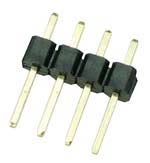
3.Male Headers
4.dc adapter power jack 2.1mm
Step 2: The Diagram


The diagram at right shows the main output connector of the power supply when viewed from the end. The colors represent the different colored wires going into it. Common colors represent common functions, ie all red wires are +5 volts, all black wires are common and so on. The connections most useful to us as haunters are the +5V (red wires) , +12V (yellow wire) and the Common or ground (black wires). Both 5 and 12 volt lines normally deliver ample current for our needs.
Of the other voltages available, the +3.3V connection delivers ample current, it's just not a very useful voltage. The +5VSB (5 volts, always on), -12V and -5V are normally very low current lines and are of little use to us.
The green wire, pin 14, is the on/off switching line. To turn the power supply on, the green line needs to be shorted to a Common line. An easy way to do this is to insert a jumper between pin 14 and pin 13.
Most power supplies require a load across one or more of the outputs to operate. The link I give above shows how to add a resistor across the 5 volt side of the supply to act as a load.
The smaller connectors coming out of the power supply use the same color codes. As an example, a connector with a yellow, a red and two black wires will have +12 volts (yellow), +5 volts (red) and two commons.
To use the power supply, for 12 volts, you'd connect a yellow wire to the + input of your project and a black wire to the - input. For 5 volts, you connect a red wire to the + and a black wire to the -.
Step 3: Short Green and Black Wires


you need to short circuit the only green wire with any of the black ground wires.You can use a small piece of wire or solder to short them or you can cut the two wires and solder them together
Step 4: Solder Your Male Headers


+12v Wire yellow Male Header , +5v Wire Red Male Header , +3.3v Wire orange male header , GND wire black male header
Step 5: Solder on Your Dc Jack for Arduino Power

One wire to 5 volts, one to ground.
Step 6: Finished

you can open up the power supply unit

Participated in the
Arduino Challenge


