

Introduction: Power Light for Glue Gun


My glue gun gets fitted with a white LED light to show that it is plugged in and switched on.
My cheap glue gun has the bare minimum of parts, and did not include any means to indicate its power status. Several times I had assumed that my glue gun was ready to use, and strained at the trigger, only to realise that it was cold.
The reverse would happen as well: I would have finished with it, and assumed that it was switched off, while in reality it was hot and just waiting to burn me when I handled it carelessly, without realising that it was hot and dripping with molten glue.
The solution to this was obvious: Fit it with a light that would be shining whenever it was plugged in to the mains. This would be great for discovering those pesky loose mains sockets, which would accept the plug and hold it in but (treacherously) not supply power to it.
The glue stick is transparent - the ones I use are, anyway - so the light is arranged to shine into the glue stick , making the part sticking off the rear of the gun glow brightly.
Warning: The entire circuit is connected directly to the mains, and so is a shock hazard. All circuit components are at high potential with respect to ground. If using it in a device with exposed metal parts extra insulation with a minimum creepage distance of 6 mm is required between parts of this circuit and the metal parts that can be touched.
Step 1: Dismantle the Gun

The first step was to unfasten the six screws holding the glue gun together and pull it apart. Inside the glue gun, there are only two shrink wrapped joins, where the mains cord gets connected to two teflon insulated wires coming from the heater. If you are careless while trying this and break off the wires like I did you will have to crimp the wires on again.
On the underside of the glue chamber is a thermistor which heats up to a constant temperature. It has a positive coefficient of temperature, and self regulates its temperature to the melting point of the glue. If it is colder, it draws more current and heats up. When it gets hotter, its resistance increases and so it draws less current and thus cools down. Thus the glue is effectively held at a constant hot temperature.
Since it gets hot solder would melt off, so the wires are crimped on to two metal plates contacting the heating element.
The modification involves soldering on two more wires to the mains cord so that the added lamp can run off the voltage coming into the glue gun.
Step 2:

Three wires join at this point: one from the mains plug, one to the heater and one to the lamp. This is repeated for the other wire.
Heat shrink tubing has been slipped over the wires before soldering. This is necessary to keep the wires from touching and shorting out.
Use the minimum amount of solder, so that the heat shrink tubing will fit over the joint. Ensure that sharp bits of wire aren't sticking out, which might pierce the insulation and cause a short circuit.
Step 3: Wires in Position

The two wires carrying power to the lamp have been soldered in position. I used a single strand peeled from an IDE flat cable for this purpose.
The joints have been covered in heat shrink tubing, shrunk using the flame from a lighter and the cable replaced in its original position. The trigger mechanism fits over this, and actuating it should not cause the wiring to move.
Over time, the copper wire near the heater assembly gets stiff due to the heat and might break at the slightest provocation. Moulded lugs in the half of this casing hold the mains cable and act as strain relief.
It is important to ensure that the wiring inside the gun is fastened down securely and is not free to flop around.
Step 4: The Circuit

This is the circuit of the lamp I am wiring into the glue gun.
The mains voltage is dropped using a series capacitor of 0.15 microfarads, 250 volt rating. A 400 volt rating on that capacitor would have been better, but I could not find one inside my collection of junk. This causes a current of about twelve milliamps when the supply voltage is 220 volts.
Those residing in 110 volt lands would have to use a 0.33 microfarad capacitor to get an equivalent effect. The voltage rating will have to be 250 volt or greater.
Two 470 ohm, 1/4 watt resistors have been used for surge limiting. Spikes on the mains, the sudden rise in voltage when the gun gets plugged in, acts of God etc cause the capacitor to act as a short circuit and the full force of the surge is borne by these resistors. One resistor by itself might not hold up, and might arc over, so the recommended practice is to use two of them in series.
I have placed them, one in each lead, just to make the assembly look pretty.
This voltage, alternating at this point, is converted into a direct voltage by the full wave rectifier consisting of four small diodes. Since the bulk of the mains voltage is dropped across the capacitor, small signal diodes are sufficent.
A 4.7 microfarad tantalum bead capacitor smooths the resulting voltage and this voltage is applied across a white 5 mm LED. This capacitor also serves to ensure the longevity of the LED by absorbing any voltage spikes that appear across it.
Step 5: Grinding Down the LED

The glue gun did not have any suitable place to hang an LED from.
In use, typically, I would place it facing away from me so the preferred place for a light was somewhere in the rear.
So, in a flash of inspiration, I decided to use the light to shine into the glue stick. Space was pretty cramped behind the trigger mechanism, so the only way to fit the LED in would be to cut a small slot in the body and file the LED flat to match.
I soldered the leads of the LED to a small scrap of copper clad board, to strengthen the leads, and applied file and sandpaper until it was flat.
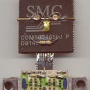
Step 6: A Flat, White LED

This is another view of the LED which was filed down until it would fit inside a slot cut in the rear of the glue gun.
The metal parts inside the transparent plastic are visible, and serve as a guide for grinding. The electrodes of the LED are held in position by this transparent plastic and if too much is removed, the LED might die a premature death.
Step 7: Full Wave Rectifier and Capacitor

The rectifier was constructed by soldering four diodes to a scrap of double sided copper clad board. The capacitor was soldered in first, then the diodes, and the free leads grouped together to make the bridge connection.
Step 8: Mains Dropper Capacitor and Surge Limiting Resistors

To the diode bridge, the two resistors are soldered and the dropper capacitor connected to one of them. This completes the circuit.
The resistors are banded yellow, violet, brown and gold.
"Bee Bee Roy has a very good wife"
This translates into numbers as four, seven, one, 5%.
The value gets deciphered as a four and a seven followed by one zero, in ohms, and a tolerance of plus or minus five per cent. ie., 470 ohms +/- 5%.
The value is marked on the capacitor, as 154 ( one, five, four zeroes, in picofarads) and the voltage rating is also written in plain numerals. The other letters refer to the grade of plastic dielectric inside it and the tolerance.
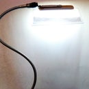
Step 9: The Entire Circuit

Walk a few steps backward, camera in hand, and take care you don't step off the kerb into traffic.
OK. here is the overall view of the LED circuit, which lights up brightly when connected to the mains.
Step 10: The LED in Position Inside the Glue Gun

Testing. It appears to be working.
I have placed the LED so that it shines into the glue stick where it enters the back of the glue gun. The light enters the stick and its entire length glows.
I used hot melt glue to fix the circuit and the LED inside the glue gun. This part of the gun stays fairly cool, so the glue should stay in place.
Step 11: A Peek in the Dark

In the dark, the glue stick glows up dramatically.
Now the status of the glue gun is instantly visible, and so that should ensure that it gets switched on and off as needed, without wastage of power or temper.
Perhaps "colour changing LED lights" would have been more appropriate for this task
Have Fun.


