

Introduction: Precision High Speed Micro Drill Press From 'Useful Material'


Fabricated precision high speed micro drill press mainly from ‘useful material’ (someone else's ‘junk’ and scrap)
My first Instructable, try not to be too nasty .
Many thanks to Andrea Biffi for posting his cheap circuit board drill press and getting me interested in making one and for comments telling me I should document my building process for an Instructable
https://www.instructables.com/id/Cheap-precision-dr...
A little background.
I consider myself a motorcycle mechanic as I’ve been working on ‘bikes’ for over 40 yrs.including almost 12 years teaching at motorcycle school in Orlando Florida until 2011. I already own all the tools, taps, dies, drills, etc from years of working on motorcycles and realise most people won't be that 'lucky' (the downside of having a 'proper job')
For the last several years I’ve been ‘playing’ with 1970’s Honda’s and Yamaha’s, specifically XS650 and CB350/360. With the resurgence of ‘Cafe Culture’ and people going for a specific ‘look’ I’ve been having fun modifying carburettors to work with aftermarket air filters (‘pods’) It entails drilling new holes and making ‘precision’ pieces, some of the holes are only 0.035mm diameter and none are over 1.5mm diameter. I needed a high speed drill press to use the available carbide drill bits, they shatter if you try to use them by hand in pin vice or if they are run too slowly in a normal drill press
Anyway, on with the build, sorry to everyone if I've oversimplified everything or should have added more steps and pictures, you can always ask in comments section, I can take pictures of the finished piece
Tools required
Drill press
Hole saws, 1.5" & 1.75"
HSS Drill bit set; I have one in 1/64” increments from 1/16” to ½”
Tapping drills for 4mm, 5mm and 6mm taps
4mm, 5mm 6mm taps and tap handle
1/4x20 inch size tap (standard thread for camera mounts - another hobby)
Countersink bit
Assorted metric screws, 3mm, 4mm, 5mm, 6mm countersunk/flat head
Divider for marking circles (compass would probably work just as well)
Hacksaw
Bench Vice
Pliers
Screwdrivers/Allen keys
Propane torch (or some way to melt lead for counterweight)
Assorted files, flat, round, etc
A lathe and milling machine would be nice but everything can be done with drill press and hand tools
Material required
1.5”x1” Aluminium box section, cut and welded at 90 degree angle – surplus store – I got lucky and the reason I decided to make 'drill press'. Steel could be used, would be easier to weld and hold threads better but more difficult to drill and tap
¾” square aluminium box section, about 1ft long
Small square piece to fit inside ¾” box section for mounting, roughly ½” x 1/2" x 1”, I had a scrap piece from some old frame (chair, window? no idea)
2 pieces aluminium 3/16” thick1-1/2 ~ 2” long, spacer/mountings - scrap offcuts, until I found a use for them
aluminium block 2.5" x 1" x 2" - off-cut I had after making a fork brace for CB360 - probably from eBay? (I forget)
Aluminium plate, about 3" square, 3/8" thick - had it in toolbox for last 20 yrs, always knew I would find a use for it
I used to get a lot of aluminium offcuts and odd bits from Skycraft (http://www.skycraftsurplus.com/) so had almost everything laying around
Pulley, I used 2”x 1/4” with 1/16” wide groove, something I made several years ago when learning machining
‘Fotomate’ camera macro rack and pinion focusing device - eBay
3.5mm steel plates –free - front axle steady plate from a motorcycle transportation crate – ask your local motorcycle shop if they have any ‘useful material’ (scrap crate parts)
¾” x1/8" aluminium angle, about 14”~18” for cross piece, came off a bench edge -free
Old lead wheel and fishing weights – I used a little over 12oz
‘Dremel’ style rotary tool - eBay - the most expensive part
4x rubber feet
Old toothbrush to make lever
2x ‘Chocolate block’ electrical connectors
18" x 1/16” dia high tensile wire ‘rope’ – I had some from a project that ‘failed’- couldn’t solder Teflon coated stainless steel wire even after coating was removed
The 99% finished item so you can see what it looks like is at top
It’s probably best to get ‘Dremel’ clone and macro focusing rack before cutting anything
When you know length of rotary tool and ‘Fotomate’ macro focus rack, you can start making some measurements for cutting box section angle piece.
Step 1: Deciding Approximate Height and Positions of Parts, Drilling, Tapping and Fitting


When you know length of rotary tool and ‘Fotomate’ macro focus rack, you can start making some measurements for cutting angle piece
The Fotomate base will give the size of extender block and move rotary tool away from main upright
The chuck doesn't need to be closer than about 3/4" to base when rack is fully extended in downward position, the drill bit will make up the difference
Cut base and upright to length, save cut off pieces.
One end already had a 45degree angle cut, I used that for extension block - the angle is useful later
Drill 5mm holes all the way through upright and extender, on center line, about 3/4" from top edge. The rearmost hole needs to be opened up large enough for a countersink bit, the next to 6mm and countersunk for flat head screw. The extender gets threaded 6x1mm and bolted to upright.
Flip upright onto back and mark/drill 5mm hole under the angle end, remove the extender drill hole to 6mm and countersink, tap hole in upright 6x1mm
Place Fotomate on extender, line up with top edge and use 5mm drill bit to mark hole position. Drill first hole, tap 6x1 and mount macro base to extender. Line everything up, use Allen key through 6mm tapped hole in back to tighten screw. Mount extender onto upright with both screws to check everything is 'square', single bolt between macro base and extender allows it to be lined up properly, countersunk screws mean extender will always go back in same position on upright. When macro base is 'right' remove extender and drill second base mounting hole 5mm through extender and macro base
Step 2: Fitting Rotary Tool to Macro Base, Top and Bottom Motor Mounts


The original pieces I had were not going to work so I made top and bottom 'motor mounts' from pieces I had laying around
Top mount
measure motor body diameter, either use caliper or measure circumference with tape measure and use math
Because of switches, brush holders, etc, top mount has to be a two piece unit. The rear of mount will be drilled and tapped on center1/4x20 for camera mounting screws (sorry, no pic of that)
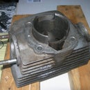
Stand on edge in drill press, drill down through close enough to edge to allow a hole to be cut for motor body (pic 1)
Lay flat and cut across centre. Open holes in outer piece to clearance 5mm Allen bolt, tap holes in inner piece 5x0.8mm. Bolt both pieces together, lay flat in drill vice and use 1-3/4" hole saw. Saw cuts slightly oversize so not much work needs to be done to correct size for motor body
Lower mount
There are no protrusions on 'nose' of rotary tool so only one clamp bolt is needed
The only thing that is real important is that the top and bottom are on the same relative centre
Back is tapped 1/4x20
Step 3: Counterweight


I was getting a bit bored so decided to 'burn stuff'
Used a stainless steel ketchup container to melt down several stick on wheel weights (without any 'stick') and a couple of old fishing weights
Used a piece of the cut off box section to make a 'mold' and a piece of coat hanger to make a loop
First attempt was a disaster, mold too cold drew all the heat out of lead. Second one worked OK, but, forgot to allow clearance for fixing bolts
Third time, added extra wheel weights to melt, pre-heat modified mold, pour, allow to cool, remove, then realise it's still too tight to fit upright (I expected some shrinkage but it didn't happen.
Beat lead with hammer, beat some more, clamp in vice and use a flat punch to flatten things out and allow sliding fit in upright. Total weight around 12 oz
Step 4: Pulley Extension, Pulley and Counterweight Cable


Use the 3/4" box section inside the extender block. At top, drill 5/16" hole on center line approx 1.25"~1.5" from top edge. Use hacksaw to make a round bottomed slot. Cross drill for pulley axle shaft and fit pulley. Remove pulley and file slot smooth so it turn free (doh)
Place motor in approximate position and realise it's a lot taller than you thought, extend pulley stand so top edge is around 1" above cable strain relief.Mark position, and use scrap pieces to fill up excess width. Drill and tap for 6mm flat head screws no critical measurements
Step 5: Cross Pieces for Stability, Feet, Work Table and Operating Lever


1. Use the 3/4" angle to make front and rear cross pieces. Clamp in position and drill through with tapping drill for 5mm screws. Countersink holes and tap 5x0.8mm in base.
Before re-fitting, drill ends for rubber feet and fit feet
2. Mark position for mounting holes on bottom of base box section. Drill through with tapping drill for 5x0.8mm thread.
Open up lower hole to allow tapping of 'top' hole but don't tap yet. Clamp steel plate in position and mark mounting hole position. Remove plate and tap holes in top surface (it's easier to work on 'front' hole from underneath, I ended up doing all of them from the bottom)
Drill and countersink 'work table', if it's radiused like mine make sure you do correct side
Last thing to do is make operating lever.I had a small triangular piece of scrap aluminium so cut it down. Drill hole for pinion wheel. cut off toothbrush handle and round one end (it's originally oval ) make a rough measurement and drill aluminium piece 90 degrees to pinion hole. I haven't finished the final step but I have marked locations on picture
Step 6:

Participated in the
Gadget Hacking and Accessories Contest


