

Introduction: Pressure Sensor Matrix


The inside looks just like the fabric pressure sensors, except each stitch is connected to a separate conductive fabric tab. The downside is that separate tabs and connections to these tabs take up a lot of space, especially if you want to achieve a tight matrix of sensors. A grid of lines and columns and some code to analyze these (separately power and measure) would allow for much tighter spacing. This version is nice because it is so simple.
To make the sensor fully fabric one can use EeonTex conductive textile (www.eeonyx.com) instead of the plastic Velostat. Eeonyx normally only manufacture and sells its coated fabrics in minimum amounts of 100yds, but 7x10 inch (17.8x25.4 cm) samples are available free of charge and larger samples of 1 to 5 yards for a minimum fee per yard.
Video
Video
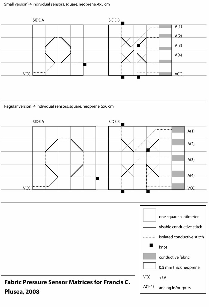
This Instructable covers two slightly different versions of the pressure sensor matrix. The only difference being the spacing of the individual pressure sensors in the matrix. In one of them they are placed practically next to each other (white) and in the other there is a 1cm space in between each sensor (purple), but because of the thickness of the neoprene it is not possible to press in between the sensors without pressuring a sensor. Hope this makes sense.
I am also selling these handmade Thread Pressure Sensors via Etsy. Although it is much cheaper to make your own, purchasing one will help me support my prototyping and development costs >>
http://www.etsy.com/shop.php?user_id=5178109
The materials used for the sensor are basically cheap and off-the-shelf. There are other places that sell conductive fabrics and Velostat, but LessEMF is a convenient option for both, especially for shipping within North America.
Velostat is the brand name for the plastic bags in which sensitive electronic components are packaged in. Also called anti-static, ex-static, carbon based plastic bags... you can also cut up one of these black plastic bags if you have one at hand. But caution! Not all of them work!
To make the sensor fully fabric one can use EeonTex conductive textile (www.eeonyx.com) instead of the plastic Velostat, but at the moment EeonTex conductive textile is only available in a minimum of 100yds. But try ordering samples!
I chose to work with neoprene because it offers a form of natural force-feedback and also it is great for sewing into with the conductive thread and thus isolating it. But you can easily replace the neoprene for some regular stretch or non-stretch fabric and even try felt or kind of rubber.
Step 1: Materials and Tools

For sensor:
- Conductive thread from http://www.sparkfun.com
- Neoprene from www.sedochemicals.com
- Stretch conductive fabric from http://www.lessemf.com
- Fusible interfacing from local fabric store or
- Regular thread
- Male headers from Sparkfun http://www.sparkfun.com/
- Arduino software free for download from http://www.arduino.cc/
- Processing software free for download from http://processing.org/
- Arduino USB board from Sparkfun http://www.sparkfun.com/
- Solderable Perfboard with copper line pattern from All Electronics http://www.allelectronics.com/
- Crocodile clips
- 4 x 10 or 20K resistors
For sensor:
- Fabric scissors
- Sewing needle
- Iron
- Fabric pen that disappears over time
- Pen and paper
- Ruler
For reading input into your computer and running an application that visualizes the changes in resistance:
- Soldering station (iron, helping hands, solder)
- Knife for cutting perfboard
- File for filing edges of perfboard
Step 2: Cut Stencils


If you don't want your sensor to look the example then you will have to decide on a shape/design of your own and create your own stencil. Otherwise you can download the stencil here >>
http://farm4.static.flickr.com/3121/3159362472_ca0e961f9f_b_d.jpg
Cut out the stencils from paper and trace on to your neoprene (or other fabric) and Velostat. You will need one square of Velostat that is a few millimeters smaller than the smaller piece of neoprene. You can use 2, 3 or more layers of Velostat to make the sensor less sensitive to light touch.
Cut out the fabric.
Step 3: Ironing Conductive Fabric Tabs


Take a small piece of stretch conductive fabric and fuse some fusible to one side of it. Cut into 5 small tabs and fuse (iron-on) along one of the shorter edges of the slightly larger piece of neoprene.
Step 4: Sewing Conductive Thread


Following the instructions on the stencil sheet, sew with conductive thread (take it single, not double) into the larger piece of neoprene, coming in from the side with a knot in the end of the thread, making one visible stitch and then sewing inside the neoprene to the appropriate tab. Stitch to the tab with a few small stitches and then plunge into the neoprene one last time and then just cut the thread and dont worry about knotting this end.
On the smaller piece of neoprene youll have all four stitches connected and then you have to sew the end of the conductive thread to the appropriate tab on the other piece of neoprene.
!!!
All this time make sure that non of the stitches are touching inside the neoprene. Do not cross them. Follow the stencil!
Step 5: Sewing Together


Place the piece of Velostat in between your two pieces of neoprene, conductive stitches facing inwards. Sew around the edges with some regular thread. You can even leave the edge with the conductive tabs open and this way you can change the layer(s) of Velostat.
Step 6: Pull-up Resistors


Test first:
Hook up a multimeter in beep mode to the VCC tab and in turn connect it to each of the other tabs. Without even pressuring it, make sure it does not beep. If nothing is touching, then you can pressure each sensor individually to see its resistance range.
Update: The resistiance range of this sensor is ideal for the internal 20K ohm pull-up resistors of the Arduino. So you can skip the rest of this step and look for the right code to activate your internal pull-ups in the next step.
Cut a small piece of perfboard with conductive copper lines, at least 6 x 6 holes big. Solder as seen in schematic illustration and plug in to your Arduino board. For more information on pull-up resistors and why they are necessary, follow this link >>
http://cnmat.berkeley.edu/recipe/how_and_why_add_pull_and_pull_down_resistors_microcontroller_i_o_
Clip the crocodile clips to the correct conductive tabs of your pressure sensor matrix.
Step 7: Run Application

For Arduino microcontroller code and Processing visualization code please look here:
>> http://www.kobakant.at/DIY/?p=3314
Program the Arduino and run the Processing application, and if everything works you should be able to see your sensor input being visualized through the graph and drawing options. See videos in the intro step.
Let me know if you have any problems.
And enjoy!


