

Introduction: Printer to Vinyl Cutter Hack


My idea is to take an old printer and turn it into a vinyl cutter, as they are quite similar in there design and it would hopefully make the build just that little bit easier.
As most people find the electronics an software the most intimidating part of a project like this, I've gone into a fair amount of detail on how to set it up. Turns out the mechanical part of this project is far more challenging, as it takes quite a bit of tweaking, adjusting and general head banging to get the vinyl to cut properly.
The video is of a test run with a marker pen.There is really not that much to see when Its cutting vinyl as its very hard to see where the cuts are until after the the vinyl leaves the machine.
Step 1: Parts You Will Need


I got quite a few of the parts from Core electronics who have lots of stuff and post it out really quickly. The rest I got from ebay which also has lots of stuff, but the post can take 2 or 3 weeks here in Australia especially if the parts come from Hong kong or China.
- dupont wires $8.18
- 10 X 40 pin headers $ 3.80
- Beginner kit for arduino At $65 it a great kit and worth a look, but you only really need the arduino to complete this project so the next link might be better.
- Arduino Uno R3 $29.95
- Standoffs $3.86
- 3mm nuts and bolts $1.07
- vinyl cutter holder 3pc blade $19.00
- 2X EasyDriver Shield stepping Stepper Motor Driver $4.09 each
- Relay Module Shield Board for Arduino $2.39
- Automotive relay $5.25 The voltage will depend on your power supply I used a 24 volt relay
Step 2: Checking Out the Printer


Of course you will also need a printer, an old one with stepper motors driving the roller and the slide. I pick up this old cannon A2 printer off ebay for $5. Back in the day it would of been worth $2000-$3000. Before I got to carried away striping the printer down I spent a few days thinking about what needed to be removed and what I could keep. First I removed the plastic cover and studied the internals of the printer, I printed a few pages and tried to get a good understanding on how everything works.
The covers came off quite easily just a knob on the side and a few clips and it all came apart.
If your not sure if you have stepper motors or normal dc motors they are quite easy to identify, steppers have 4 or more wires coming out the back and they are usually quite a large diameter and short. So look for short and fat motors with 4 wires.
Step 3: Mounting the Arduino, Easy Drivers and Relay


Once that was done it was time to start using some of those dupoint wires, they make every thing very easy to wire up Just pull a pin out of the headers and plug it in if you want to make the end of the wire male.
The next step will show you where all the wires go but first we need to identify the four wires on our stepper motor.
- Set your multimeter to the 200 ohms setting
- Grab any 2 wires on you stepper motor and check if you get a reading you should get either open circuit or a low resistance.
- If it was open circuit, grab another wire and check that, you are looking for a pair of coils inside the motor, so you need to match up to ends of each coil (which are connected to to each wire)
- Once that is worked out, I cut a dupoint lead in half and soldered each end on to the matching pair of wires. Because th leads are the same colour I know that is on coil.
- Repeat the process with other 2 motor leads and the other motor
- Next I identified the wires coming out of the power supply and the voltage which turn out to be 28 volts.
- Make sure that you check the polarity of your power supply and wire it up correctly or you will have lots of smoke and swearing. Use a red and black wire.
- I found that the easy drivers do get quite hot so a bit of thermal grease and an old heat sink helped keep things cool.
Step 4: Wiring Up the Ardunio


- Motor coil A and motor coil B connect to the stepper motor It doesn't matter which way around as long as A goes to one coil and B to the other coil
- The Power in - + pins go to the power supply and you need to get these around the right way and up to 30 volts DC
- On the lower right there are 3 pins GND (ground) STEP and DIR(direction). GND goes to GND on the arduino
- Note there are usally 3 GRN pins on the ardunio board it doesn't matter which one you use.
- On the X axis driver STEP goes to pin 2 and DIR goes to pin 5
- On the Y axis driver STEP goes to pin 3 and DIR goes to pin 6
- We wont be using the z axis in this project.
- The vcc pin goes to the 5V ( 5 volt) pin on the arduino
- The GND pin goes to GND on the arduino
- The IN1 pin goes to pin 12 on the arduino
Step 5: Installing the Software

Ive loaded most of the software on a Mac laptop, and it works, with the exception of the X Loader which I had to load onto a windows machine. (more on that later)
If you use windows I'm sure it would be easier.
so here's the list
- Arduino Software
- Grbl Controller
- Inkscape
- Xquartz Is needed to run Inkscape if you use a Mac
- Grovers Laser engraver add on (Ive put the file on the the bottom as the link is blocked from some schools)
- Xloader ( I was unable to get this to work on a mac so I used a windows machine)
- The hex file which can be a bit hard to find on the internet so its also zipped.
- instructions for setting up Xloader on different operating systems if you get stuck
- Eggbot May help if your Mac decides it doesn't want to play with laserengraver

Step 6: Getting the The Arduino and Computer to Play Nice.


Once the Arduino board has been flashed with the X loader program you will no longer be able to use it with the Arduino software, however you can then use grbl on windows or a mac.
I have a few screen shoot of the Mac version of Arduino and Grbl as they are slightly different to the windows version
- First thing to do is to plug in you Arduino board and open up the Arduino software to get the board talking to your computer.
- In the tools pull down tab you will find serial port you can choose from
- If your not sure which one to choose, go into Start / control panel / system / hardware / device manger / ports (com & lpt)
- That should tell you which com port to select.
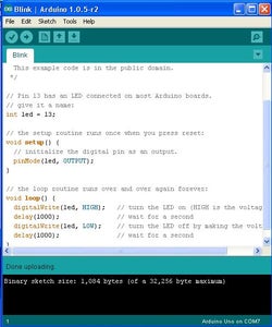
- Double check that everything is working by running a sketch. On the Arduino software file / examples / basic / blink.
- Now hit the arrow button below the "edit" tab and you should see the Aruduino board light up and a "message done uploading" at the bottom of the screen
- Now open up Xloader and select the hex file, the device (uno) and the com port
- Warning once you hit upload you wont be able to use the Ardunino software on that board.
- Hit upload and give it a minute or 2 until you see the upload done message.
- Now open Grbl and choose the com port
- Once you click on the open button, you should see text scroll down the page
- Fist install arduino and go to tools / serial port and choose one of the ports with usb in the name e.g. /dev/tty.usbmodemfa131
- Run a sketch just like in windows to check everything works.
- Grbl will not work unless you have installed Ardunio first.
- Flash you Arduino board using xloader on a windows machine.
- Install Grbl and choose the correct serial port and every thing should work
Step 7: Modifying Inksape


Ive done this on a Mac computer but I have since found out it may not work on all mac computers, it depends on what version OS you have.
- First install Xquartz and then Inkscape, the links are on step five.
- The install can be a bit grumpy so take your time and restart when finished.
- Once you have inkscape running close it down and go into Applications / inkscape / (right click) / show package contents.
- You will find a folder Contents / resources / extensions /
- Now copy the files from you laser engraver folder you downloaded . There are 4 files
- Paste them into the extensions folder and click on "replace"
- Now open Inkscape and you should have and extension named laserengraver.
- When you click on it it should pop up with a laser box
- This step I found the most frustrating. Under the preferences tab you need to type in the path to where you Gcode will be saved. By default inkscape seems to hide the file somewhere Ive never been able to find.
- Try /Users/"yourname"/desktop I have seen other variations it depends how your laptop is setup /Users/volumes/"yourname"/desktop
- If your Mac still dosnt want to play with Laser engraver try installing eggbot the extension It seem to fix the laserengraver,
Step 8: Test Run With No Blade


I noticed that the mac version can be a bit gitchy as the new setting don't seem to work sometimes but hitting the big red close/reset button seems to fix it usually.
If you look on the first screen shot notice the 3 tabs Axis control, Visualizer and Advanced. There is also a step size tab on the bottom right and arrows to step the X Y and Z Axis
You can make your printer roller and slide move by clicking on each arrow, If things are going the wrong way or moving on the wrong button you can fix this by correcting your wiring on the easy driver to motor connections. To change direction of the motor, reverse the connection on one motor coil.
Warning Dont change any connections with the power on it will damage the easy driver boards.
Time to start playing with the setting. (Notes are also on the screen shots)
- We need to change The X and Y setting so the slide and paper move the correct distance. Note the $0=250.000(X,step/mm) and the $1=250.000(Y,step/mm)
- Click on the advanced tab then click on Unlock Grbl then Grbl setting
- Click on the stetting you want to change, The roller was travelling way to far so I reduced this to 29.5 ( yours will probably be different) so the paper would move exactly 100 mm when the 100mm step is selected.
- Hit apply and on the main screen hit soft reset
- All going well you should see a new line of code at the bottom of the text screen. You can then use the arrows to see if your changes worked. (If nothing changed hit the red reset button)
- Once you have on axis moving the correct distance you can adjust the other.
- You can also adjust the speed Under the default feed and default seek
- You will find that speed doesn't change that much until you adjust the acceleration
- I got mine setting by trial and error, with the goal been to draw a 100mm square box, it to about an hour of fiddling
- I then found it was all back to front so a quick wiring change to the X (slide) stepper motor fixed that.
Step 9: Adding a Surface for the Blade


The blade needs a surface that is slippery and a bit softer than steel so that it is not damaged when cutting. I used a strip of plastic with double sided tape, just make sure that it is perfectly flat and the is no sharp edges for the vinyl to get caught on.
Step 10: Removing Unnesary Hardware


I found that there was a few things that could be removed as they were just creating drag as the spun with the roller. So the tractor drive was removed and a couple of gears also.
Step 11: The Electromagnet


The electromagnet was removed from a 24 volt automotive relay and is used to pull the cutter down onto the vinyl. Its just a case of removing the cover and pulling the contacts off, so you end up with a coil. This is then wire back to your power supply and the relay attached to the Arduino is used to control it.
The internals of the printer head are removed and after some trimming, cutting and careful positioning the coil can be put in place.To test it you can use the spindle on tick box in grbl and this will turn the relay off and on.
Positioning the coil is quite difficult as it need to be square, flat, and not quite touching the cutting plate when energized. I spend quite a bit of time getting it just right before gluing it down with rapid fix super glue.
Just a note on the rapid fix super glue, if you can get it it is the best glue that I have ever used. It like super glue on steroids and it comes with a powder that can be used to fill large gaps or holes
Step 12: Fitting the Cutter


As with the electromagnet, this part was also very time consuming and fiddly. I used a 3D printer to make a holder for the cutter and also some little brackets to hold the tube and spring from a ball point pen. The idea of the pen spring is to lift the cutter off the vinyl when the magnet is not energized,
Again everything has to be aligned perfectly and the spring tension has to be just right so the cutter moves away from the vinyl but not so far that the electromagnet is unable to pull it back.
I made an interesting discovery, that is I placed a button rare earth magnet on the back of the electromagnet it made the electromagnet much stronger and work more reliably. (This is a bit hard to see in the photo I've put a note box on the photo with the yellow vinyl)
I then used the rapid fix glue to fasten everything down.
I also found that as the printer has a couple of gears in the mechanism, the tiny amount of backlash they have, was causing some of the cuts not to join up by about 1/2 a mm. Very annoying when you go to remove the wast from the sticker, so I will move the stepper motor so it directly drives the roller.


Step 13: Work Flow


The Screen shot have notes.
- Open up Inkscape and click on file/ document properties
- Next change the default units from px to mm you need to do this in 2 places
- Now File / Import your drawing and select the drawing you want
- A box will pop up just click ok
- Your image should appear on the page and can be moved or re-sized The cutter starts from the lower left corner so you want to make sure its moved close to that point
- Under the path tab click on trace bitmap
- A pop up box with lots of settings to play with will appear click on update and ok when you are finished. The image should be made of solid blacks lines when finished.
- When you go back to your image on the page it looks like nothing happened, drag the trace off the top of the original image
- Now delete the original image and move it to where you want on the page (macs have no delete key use control delete)
- Now under path click on object to path
- click on extensions Laserengraver
- In the pop up box make sure the Directory path is correct and click on the laser tab
- Turn the speed up to 1000 but dont click on apply yet. There is a glitch here that cause an error if the laser tab is open
- Click on preferences again now hit apply
- You should get a laser working box and a Gcode will appear on you desk top
- If you would like to the workings of a Gcode you can open it with text edit
- Open up Grbl and click on choose file and find your Ggode
- You will now be able to see your tool path
- Once you click on "begin", the machine will start working, you can follow the tools progress with the red dot and green lines on the screen
Step 14: Applying the Sticker


If you pull off the wrong piece or get some of the waste stuck on the rest of the sticker, or a part hasn't quite cut right and you pull that off, its very difficult to fix and in most cases you will have to start again. So here my top tips for success.
- Start from the outside, and if the waste is quite large cut it into smaller pieces with a sharp knife or box cutter before you pull it off
- Be very aware of where the waste is (I screw it up into a ball as I'm working) It only takes a a second for it to touch your sticker and it nearly impossible to remove.
- As you peal pieces off some small parts may be lifted off as well so take your time and use your knife to push these parts back on to the backing paper.
- Use a small knife to flick and small pieces out and it doesn't matter if you damage them sometimes stabbing a piece its the best way to remove it
- As soon as you have finished removing the waste, cover the sticker with masking tape as this will protect it from damage and it is now ready to apply
- Clean and dry the surface you want to apply the sticker to.
- Carefully remove the masking tap and the sticker will come off with it.
- Apply the sticker to the surface and watch out for wrinkles
- Rub it down with your fingers and slowly start pulling the masking tape off.
- Sometimes parts of the sticker will want to come off with the tape, just push it back down and rub it again and pull the tape off from a different direction.
- Once the tape is off rub the sticker down with your fingers.

Runner Up in the
Arduino Contest

Third Prize in the
Full Spectrum Laser Contest

Second Prize in the
Green Electronics Challenge

Participated in the
Gadget Hacking and Accessories Contest


