

Introduction: Programmable Keypad


I recently got an internship with a company that is a distributor of industrial products such as hydraulics, pneumatics and various other mechanical and electrical devices. My most recent assignment was definitely work for an intern. They have an online store with tens of thousands of products and lucky for me, approximately half of these items did not have an associated picture or datasheet. My job, to take this giant speadsheet of pictureless items and search for them online and the save the pictures in one folder and the datasheets in a separate folder.
Now after the first day of constant copying and pasting, and having to change the folder I was using, my hand hurt and I was tired of the repetition so I got the idea. I had an idea earlier in the year to make a little keyboard that I could use for symbols when writing a lab report, like the ohm symbol, micro symbol, etc. Well I never did do that but I had all the parts for it so I decided to finally make this project and use it to help me at my job.
I would like to point to an episode of SparkFun's Engineering Roundtable that gave me the headstart to do this project. It can be found here.
Step 1: Materials
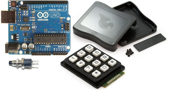
Arduino Uno(https://www.sparkfun.com/products/11021)
Keypad(https://www.sparkfun.com/products/8653)
Sparkfun enclosure(https://www.sparkfun.com/products/8601)
Small pushbutton, NO(already had)
USB cable(already had)
Ribbon cable with headers or jumper wires
Step 2: Setup

To get started, I looked at the pictures of the keypad on the Sparkfun website, specifically the picture with the buttons removed. This allowed me to trace the tracks and figure out which pin corresponds to which row or column of the keypad. After doing this, I loaded up the example keypad sketch from the Arduino website (here). I loaded this code just as a base and used it to make sure that all of the pins were assigned correctly using the serial terminal to confirm.
Once I found out which pin was which, I assigned each one to an Arduino pin.
Keypad-----Arduino
1-----9
2-----8
3-----7
4-----6
5-----5
6-----4
7-----3
Step 3: Connecting the Keypad to the Arduino

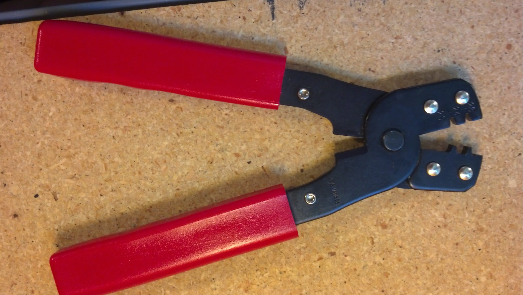


I used a ribbon cable to connect the keypad to the Arduino. You could get one that already has some male headers on them, but I made my own. I used what I believe are called 'Dupont' pin headers and housing that I got from eBay. I crimped all 7 wires on both sides then aligned them into the housing. I used one 7 pin housing for the keypad side and one 5 pin and one 2 pin on the Arduino side so that I could jump the gap between the headers on the Uno board.
Before soldering the pins onto the keypad, I bent them at a 90 degree angle so they would fit better into the case. And be sure that you pick the correct pins from the keypad to put into the 5 pin and 2 pin headers for the Arduino, but if you do put the wrong ones, it is easy enough to adjust the Arduino code to compensate.
Step 4: Mounting the Arduino


When you are placing your Arduino in the case, it would be ideal to use some plastic or nylon standoffs. Unfortunately, the standoffs that I had available (3/8" height) were too tall and the case would not close. This caused me to just hot glue my Arduino to the case. There is a little flat spot that doesn't have the standoff points which is where I put a big glob of hot glue to stick down my Arduino. I chose to place the Arduino so that the backplate would still fit on and the USB port would be pushed up against it. You could also have the USB port stick out a little to be flush with the backplate after completion.
After I had my Arduino in place where I wanted it, I slid the backplate on and marked where the USB port was. I then cut out the mark so that I could plug in a USB cable easily. I thought about making the USB cable permanently attached but I went with this way because I think that it gives it a cleaner look and makes it easier to transport.
A hole also needs to be made so you can easily reset the 16u2 USB chip. This hole can really go anywhere since the button is connected you wire.
Step 5: Adding the Reset Button


A small normally open push button is needed in order to reprogram what each button does on your Keypad. To attach the the button to the Arduino, you will need to attache some small wires to it that have a 2 pin female header on the opposite end. I used the same type of pin header that I used on the Keypad to Arduino ribbon cable.
The pins that the button are attached to need to be bent to allow the case to close properly. I used a flat head screwdriver to gently bend them about 45 degrees. Be sure not to bend them too far or when you put the connector on, it may wedge the Arduino's reset button down and you could end up with random resets during use.
Step 6: Arduino Code

After I had the right pins assigned in the basic keypad code, I started to add the necessary code to use an Arduino Uno as an HID keyboard. Here is all the reference for the mouse and keyboard libraries that are used on Arduino. This is a good learning spot to see what everything that will be in the code means. After downloading the library and adding it to my "Libraries" folder in Arduino, it's time to start coding! Attached is my final code, the most recent one is the 'LH_keyboard' that I made for work, you'll notice that I only used 4 of the available 12 buttons, this is simply because I only needed four macros for what I was doing. This is easily extendable to fit any of your needs. This code is pretty self explanatory and simple. All it does is wait for a key to be pressed, then based on which one was pressed, types out a certain keystroke. The four buttons used on my keypad were programmed to copy, paste, and do a save/save as in two different locations. To get the keyboard library to recognize certain special characters, such as slashes or quote marks, you must use the ASCII representation of the symbol and send it using "keyboard.pressKey(ASCII);", where you replace 'ASCII' with the corresponding number found on an ASCII table.
Attachments

Step 7: Flip


In order to have your computer recognize the Arduino Uno as a keyboard, we need to reprogram the Atmega16U2. This is the small chip that handles all of the USB controls. We can program hex files onto it using Atmel's Flip software, here. You will also want to download the appropriate hex file from here. The preloaded hex file can be found in your Arduino folder, \hardware\arduino\avr\firmwares. To get the USB chip in programming mode, you must short the reset pin to ground. This can be simply done by taking a header jumper and temporarily connecting it across the two pins that are closest to the RESET button on the Arudino Uno. Not the pins in the female headers, but the pins on the male headers shown in the picture.
After you have Flip installed, run it and have your Arduino plugged into your computer. Reset the Atmega 16u2. Click on you USB cable icon in Flip and select USB. Select the button that looks like an IC and choose the correct device. Now you're ready to load the hex file! Click File, Load HEX File and navigate to the keyboard hex file downloaded from above. After loading it simply press Run and wait for the process to finish. This usually only takes a few seconds. After the chip has been reprogrammed, kill power to the Arduino and start it back up. Now when you plug your Arduino Keypad into your computer it will be seen as a keyboard!
Step 8: Reprogramming
To reprogram the buttons on your keypad, you need to reload the original hex file onto the 16u2. Then re-upload your Arduino code, load the keyboard hex file and you're good to go!
If you use an Aduino Leonardo or Micro I am pretty sure that the need to reprogram the 16u2 is obsolete, as they are only single chip boards.
See Updates!
ENJOY!!!!!
Step 9: Updates


6/26/2013
I have made one major update to the keypad since starting it. That is, I replaced the Arduino Uno with the Arduino Leonardo. REally all this did was eliminate the need for the reset button on the Uno's 16u2 USB controller. One drawback to this is that it uses a USB Micro connection, which doesn't stick out as far as the USB type B, making it a little bit harder to mount in the same case. Also, the DC power jack got in the way for me, so I just removed the whole thing. This replacement should make reprogramming it simpler.
I managed to avoid getting a whole new case and keypad. Luckily, SparkFun sell just the backplate for their project case, and it's cheap at only $0.50! I just took a new one of these and cut out a small hole for the USB micro connection. (SparkFun project box backplate)
The programming was changed slightly and I have included a blank template, one for use with the Leonardo and one for use without it. Some of the syntax is different, such as special characters. Reference for those can be found here.
Attachments
Step 10: Update
I now use a Pro Micro instead of the Uno or Leonardo. This allows me to use the built in Keyboard function. I have also used this to create a keypad for use with the Eagle layout software for making schematics and PCBs. My new source for this is attached. There is a switch added to pin 2 so that you can switch between PCB and schematic commands...Enjoy!
Attachments

Participated in the
Epilog Challenge V

Participated in the
Arduino Contest


