

Introduction: Programming an ATTiny13A Using Arduino & Servo Interpreter


So there I was, browsing eBay, looking for some cheap deals on Atmel chips when i came across a pair of ATTiny13 chips for £2.50. I just had to have them! After all, how hard can it be?
I needed a small chip to read servo signals from a hobby RC Receiver and control a laser output.
Once they arrived it dawned on me that I actually had no idea how to program these little chips. Dom and I spent hours trying various ways of ATTiny programming we found online with no luck. It was only until he left I sat down at my computer and found Tekstop's tutorial on 'Tiny programming that I had any success. With a couple of modifications to his files you will be up and programming these low price chips in no time!
Step 1: Connecting an ATTiny for Programming

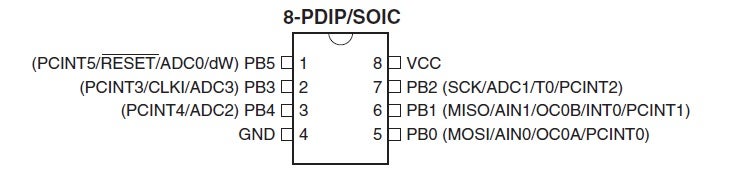
Connect your ATTiny13A to your arduino following the diagram below
Arduino pin 12 - ATTiny pin 6
Arduino pin 11 - ATTiny pin 5
Ardunio pin 10 - ATTiny pin 1
Arduino +5v - ATTiny pin 8
Arduino GNd - ATTiny pin 4
Optional:
GND - negative side of LED
ATTiny pin 3 - resistor (250 ohm) - positive side of LED
ATTINY13A Datasheet: http://www.atmel.com/Images/doc8126.pdf
Arduino ISP info: http://arduino.cc/en/Tutorial/ArduinoISP
Step 2: Setting Up the IDE

- Open the arduino IDE and connect your Arduino
- Go to file > Examples > ArduinoISP
- Check you have the correct board & port selected (Tools > Board/Serial Port)
- Press the upload button
- Once complete, close the IDE
- Download and extract this file: https://github.com/tekstop/attiny/tree/Arduino1
- Copy the folder "attiny" from the extracted ZIP to the /hardware/ folder in your arduino IDE installation directory
- Open Hardware/attiny/boards.txt
- Scroll to the bottom of the file, this last few lines contains the data relevant to our chip
- Change "attiny13.build.f_cpu=9600000L" to "attiny13.build.f_cpu=1000000L"
- Open the Arduino IDE again
- Go to Tools>Board and select "ATtiny13 (internal 9.6 MHz clock)"
Step 3: Programming
- Open the IDE
- Click File>Examples>Basic>Blink
- Change line 11 from "pinMode(13, OUTPUT);" to "pinMode(4, OUTPUT);"
- Change line 15 from "digitalWrite(13, HIGH);" to "digitalWrite(4, HIGH);"
- Change line 17 from "digitalWrite(13, LOW);" to "digitalWrite(4, LOW);"
- Click File>Upload using programmer
Once this is complete (~5 seconds) your LED should start blinking with a 1 second interval
To address pins in the Arduino IDE you should use their PB number from the diagram below (EG Pin1 = PB1 etc..)
If all you wanted to do was learn to program your chip, then congratulations! You are done!
If you would like to build a RC Servo Interpreter then keep reading.
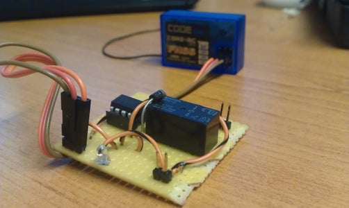
Step 4: Building the Servo Interpreter
Code is available in attached text file.
Connect the LED and resistor in exactly the same way as Step 1 states for testing purposes
If you use a relay it should be rated at 5V for the coil.
Connect the coil between pin 4 and GND
If using a relay you should also use a diode to protect the ATTiny from EMF by wiring it across the relay coil, negative(white band) side connected to pin 4.
Attachments

Step 5: Testing 123

Participated in the
Remote Control Challenge

Participated in the
Hurricane Lasers Contest


