

Introduction: Programming the ATtiny85 From Raspberry Pi


These instructions tell you how to setup and program the ATtiny85 microcontroller from a Raspberry Pi via the SPI interface. Lots of people use the Ardiuno to do this (then you can use the Arduino IDE and simplified C commands), or you can use a USB based programmer. I do not have an Ardiuno and don't want to buy a dedicated programmer. I do have a Pi, so I was pleased to learn I could use it as a way to get into microcontroller programming.
You will need:
Raspiberry Pi
ATtiny85 chip
5 x 1K resistors (or similar)
LED of your choice
A connection to the GPIO of the Pi, and a breadboard and wire.
Based on https://www.instructables.com/id/How-to-program-ATt...
and http://www.raspberrypi.org/phpBB3/viewtopic.php?t=...
and https://www.instructables.com/id/RGB-LED-Mood-Light...
https://www.instructables.com/id/ATTiny4585-LCD-display-control-with-a-shift-regis/step3/Programming-the-ATTiny85-with-a-test-program/
Step 1: Setup the Raspberry Pi

At the terminal of the Pi:
Download and build avrdude
sudo apt-get install bison automake autoconf flex git gcc
sudo apt-get install gcc-avr binutils-avr avr-libc
git clone https://github.com/kcuzner/avrdude
cd avrdude/avrdude
./bootstrap && ./configure && sudo make install
Setup SPI on the GPIO
sudo raspi-config
and Enable SPI device in the Advanced Options (see picture)
You can check this at the command line with lsmod, no need to reboot. (Maybe need to sudo modprobe spidev)
Download and build WiringPi for the gpio commands
cd ~
git clone git://git.drogon.net/wiringPi
cd wiringPi
./build
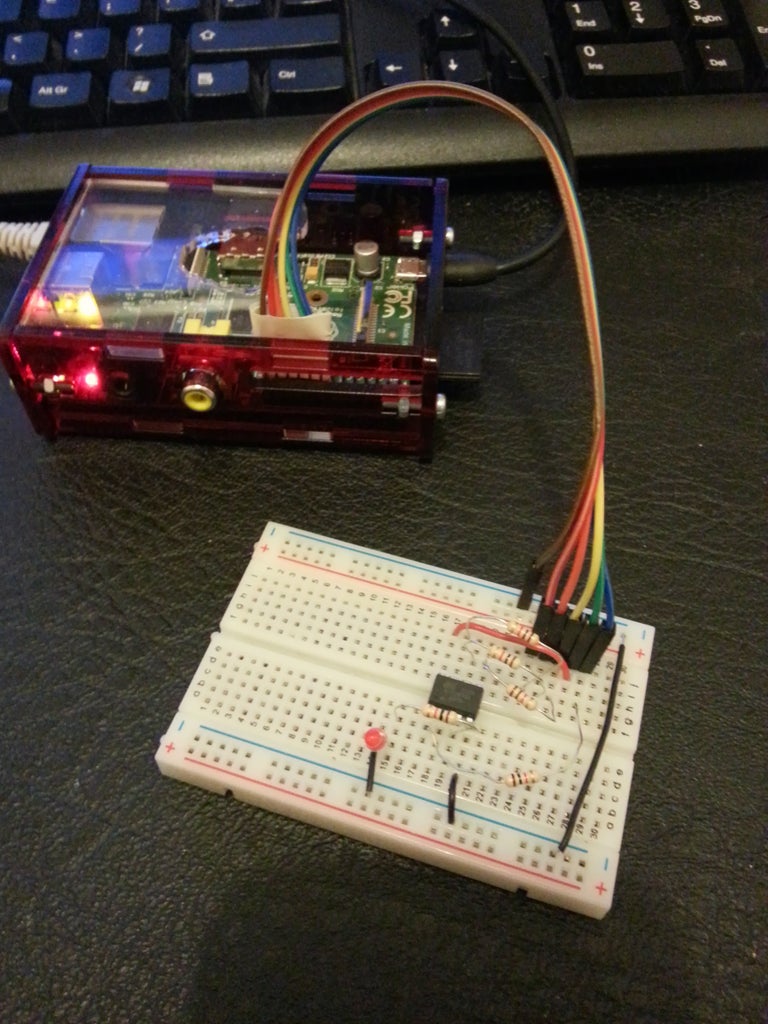
Step 2: Electrical Connections

Connect up the ATtiny85 to the Raspberry Pi GPIO (wire colours from the picture are given for reference):
GPIO pin ATtiny pin Comment
15 1 GPIO22 to Reset (through 1K, Blue wire)
17 8 3.3 V (Green wire)
19 5 MOSI (through 1K, Yellow wire)
21 6 MISO (through 1K, Orange wire)
23 7 SCLK (through 1K, Red wire)
25 4 GND (Brown wire)
(I could not find a way to do a nice table in instructables)
Step 3: Test Avrdude Connection

Test avrdude connection to the ATtiny85, we are set up with GPIO pin 22 on the ATtiny reset. We must pull this pin low to program the chip. This can be done in other ways, e.g. a switch, but I an using another pin of the GPIO to do this.
sudo gpio -g mode 22 out
sudo gpio -g write 22 0
sudo avrdude -p t85 -P /dev/spidev0.0 -c linuxspi -b 10000
sudo gpio -g write 22 1
This must give success type messages!
Step 4: Program the ATtiny85

Program the ATtiny85:
cd ~
mkdir ATtiny85
cd ATtiny85
mkdir blinky
cd blinky
create the blinky.c file and add the following code
nano blinky.c
////////////////////////
#define F_CPU 1000000L
#include <avr/io.h>
#include <util/delay.h>
int main(void)
{
DDRB = 0xFF; // PORTB is output, all pins
PORTB = 0x00; // Make pins low to start
for (;;) {
PORTB ^= 0xFF; // invert all the pins
_delay_ms(100); // wait some time
}
return 0;
}
////////////////////////
add this code to a Makefile file
nano Makefile
///////////////////////
MCU=attiny85
AVRDUDEMCU=t85
CC=/usr/bin/avr-gcc
CFLAGS=-g -Os -Wall -mcall-prologues -mmcu=$(MCU)
OBJ2HEX=/usr/bin/avr-objcopy
AVRDUDE=/usr/local/bin/avrdude
TARGET=blinky
all :
$(CC) $(CFLAGS) $(TARGET).c -o $(TARGET)
$(OBJ2HEX) -R .eeprom -O ihex $(TARGET) $(TARGET).hex
rm -f $(TARGET)
install : all
sudo gpio -g mode 22 out
sudo gpio -g write 22 0
sudo $(AVRDUDE) -p $(AVRDUDEMCU) -P /dev/spidev0.0 -c linuxspi -b 10000 -U flash:w:$(TARGET).hex
sudo gpio -g write 22 1
noreset : all
sudo $(AVRDUDE) -p $(AVRDUDEMCU) -P /dev/spidev0.0 -c linuxspi -b 10000 -U flash:w:$(TARGET).hex
fuse :
sudo gpio -g mode 22 out
sudo gpio -g write 22 0
sudo $(AVRDUDE) -p $(AVRDUDEMCU) -P /dev/spidev0.0 -c linuxspi -b 10000 -U lfuse:w:0x62:m -U hfuse:w:0xdf:m -U efuse:w:0xff:m
sudo gpio -g write 22 1
clean :
rm -f *.hex *.obj *.o
///////////////////////
(Sorry, the instructables text editor has destroyed all the tabs and spacing in the code above, the Makefile will not work without tabs in the correct place)
To compile type:
make
To compile and upload code to the ATtiny:
make install
To optionally send fuses:
make fuse
This program oscillates ALL 5 pins as outputs so the LED should flash.
We are programming the ATtiny directly using avr-libc.
To change the setup of the ATtiny get fuses from : https://github.com/kcuzner/avrdude


