

Introduction: Put a Cylon in It!


Last year the comedy sketch show 'Portlandia' made fun of an arts and craft trend, where craft artists would take ordinary items and 'put a bird on it'. I fell victim to a similar trend in the geek crowd: Take an ordinary silver item and add LEDs to 'put a cylon in it'. :)
When I saw the Total Control Lighting strands, the first thing that came to mind was sticking these on the front of my Jeep to create a 'Cylon Eye'. Installing them in the Jeep was a breeze, which then freed me up to tinker with the software. I now have a multi-mode Cylon Eye with a pretty purple control module in my Jeep.
In this Instructable, we'll be working with Total Control Lightings strands, Arduino programming, and the all new "Total Control Lighting Developers Shield Project Housing" that Cool Neon will be releasing at the upcoming 2013 Maker Fair in San Mateo California. (You saw it here first, folks!)
Parts List:
- Total Control "Awesome Dev Shield Box" Kit ( Seeeduino & TCL Developer's Shield wrapped in a
lovely Purple Anodized housing)
- 25 pixel Total Control Lighting strand (bullet shaped pixels)
- 1 TCL 4-pin male connector
- 1 TCL 4-pin female connector
- 12ft 4-Conductor 22-guage Lead Wire
- 12v -> 5v power supply (For this Instructable I'm using a cigarette->USB 5v adaptor)
- USB mini cable, for programming and power
- zip ties!
- velcro or mounting screws, depending on your level of permanence desired. :)
Tools needed:
- Drill
- 7/16" drill bit
- 1/16" drill bit
Also required is an awesome wife who is willing to let me drill holes in our jeep. Thank you Melanie! I love you!
UPDATE 2016-06-17: Final tweaks and notes
Step 1: Program the Controller and Test

I know this sounds crazy, but before we get to the fun part of drilling holes in the front of the Jeep, let's program the controller and test it all out. This will give you a chance to play with the controls and more easily see the resulting changes than when the LEDs are mounted and the controller is in the vehicle.
For the programming/testing stage, you only need four things:
- The TCL Controller
- a 25 pixel strand of TCL lights
- USB mini cable
- a computer with the Arduino IDE installed.*
I have a few code packages available for this project. One is CylonEye, HippieCatcher, and HippieCatcher "Road Safe".
These are rough drafts, to be kind. I'll be posting cleaned up code with better comments in a few days.
CylonEye does exactly what you would expect, and a little more. It utilizes the switches and pots on the developer shield to give the user many behavioral modification options without having to rewrite the source.
HippieCatcher functions like a digital 'cow catcher'. For those too young, a 'cow catcher' was a plow-like contraption on the front of locomotive engines that deflect cows off of railroad tracks so as to prevent train derailments. Similarly, the HippieCatcher code cycles through and endless series of morphing colors that start in the center pixel and flow outwards towards the edges. HippieCatcher also makes used of the developer shield inputs to adjust the visual display.
HippieCatcher "Road Safe" is the same as above, but it limits the levels of blue light to keep you street legal.
CylonEye - Cylon_v0_10.ino.zip
HippieCatcher - HippyCatcher_v0_10.ino.zip
HippieCatcher "Road Safe" - HippyCatcher_roadsafe_v0_10.ino.zip
More on the tunable options later.
For now, connect the TCL strand to the four-pin output cable on the TCL controller. Then connect the TCL controller to the computer using your USB cable. I use a dual-head portable hard drive USB cable, which increases the amount of power available to the TCL system. Upload the code of your choice to the controller, and make sure the lights start morphing.
With the controller, TCL strand, and programming verified; we are ready to install the pixels in the vehicle.
*If you are trying to program a Seeeduino (or TCL Developer Controller) on OS X Lion or Mountain Lion, you will need to install FDTI USB drivers. I have a blurb about this on my blog thing. Once you have the drivers, the correct Board is "Arduino Duemilanove / ATMega 328" and the Programmer is "Arduiono as ISP".
Step 2: Installing the Smart Pixels


These instructions are for my Jeep Wrangler, and they may not be even close to what you need to do for your vehicle. Your mileage may vary. Measure twice, cut once. Etc.
First step was to take the front panel off my Jeep. There are six pop-pins along the top of the panel. Once these are removed, the front panel swings right out.
To get a nice straight line, I took a piece of 3/4" thick wood trim and rested it on the back side of the tops of the air inlets, and then I drew a line. I made a mark on this line in the exact center of the panel. Using a compass, and working outward from the center mark, I made additional marks every inch.
Using a 1/16" drill bit, I drilled starter holes at each of these marks. I wasn't paying enough attention, and I made two more holes that I needed. Don't do that. You can learn from my mistakes!
Using the 7/16" drill bit, I drilled through the starter holes.
I pushed through the pixels, and zip tied down all the slack in the wires.
I re-installed the front panel on the Jeep, and re-inserted all the pop-pins, making sure the connector for the strand was accessible.
Using the 12' of 4-conductor lead wire, and the pair of male and female connectors, I made a TCL extension cord. I then fed this through one of the Jeep's convenient ports in the engine compartment firewall and into the passenger compartment. Then I secured down the lead wire with zip ties.
I attached the control box to the dash with a little Velcro. (Picture coming)
Step 3: Total Control Developer System

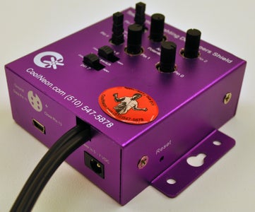


This addendum is all about the Total Control "Awesome Dev Shield Box" Kit. It's an all-in-one Seeeduino with TCL developer shield, wrapped in a pretty purple housing. Made exclusively by Cool Neon, and being released this weekend at the 20-13 Maker Fair.
It contains a Seeeduino controller that can be powered via USB or the 5V power port. The Seeeeduino is based on the Arduino Duemilanove but with a couple of tweaks. The reset button is on the side, so that it is not obscured by shields. Surface mount components are used to free up additional space for I2C and Serial Grove connectors. 3.3v / 5v selectable. M_RST_AUTO switch to disable the controller resetting if the USB host power cycles.
The TCL Developers Shield adds two on/off switches, two momentary contact switches, and four pots. And then there is the awesome housing.
Step 4: Final Tweaks


It's been a year, and I had a couple last tweaks I've added to this project that I wanted to share.
Several of the iterations of controller code have made use of the potentiometers to make on-the-fly adjustments. That was fine when I had the pixels and controller hanging off my desk. Not so fine after I installed it in the Jeep. Every time I tweaked the color or speed I'd have to get out of the Jeep and check the effect. Using a strip of nine high-density WS2812 LEDs, and a couple of code tweaks, I added a preview display to the controller. No more running to the front of the Jeep to see if I have just the right shade of purple.
Unless someone finds an outright bug, I'm done tweaking the source code as well. It has six documented modes, and one anti-documented mode. Play with it, I think you'll find it does all it can for what it is.
https://github.com/ghstwhl/cylon_eye
OK, OK, OK... One last tweak... As implemented, the preview display was just too bright after dark. So, I wired a CdS photocell to A5, with a 1k pulldown to ground, and tweaked the code one last time. Now the preview display auto-dims as the lights go down. How cool is that? The new code has been pushed to github, and it will likely be very erratic if you run it without the CdS cell.

Participated in the
Epilog Challenge V


