

Introduction: Qtechknow Robot Obstacle Course


Have you ever thought of controlling your FuzzBot wirelessly? Do you want to make a real - life video game? Do you want to learn about the tech behind NFC and RFID? - the Qtechknow Robot Obstacle Course How - To Guide is for you!
Please cast your vote for me (at the upper right hand corner, the orange ribbon) in the RC Contest, Tech Contest, and the Microcontroller Contest!
What does it do, how does it work?!
Thanks to Matt for the awesome Hackaday article + interview!
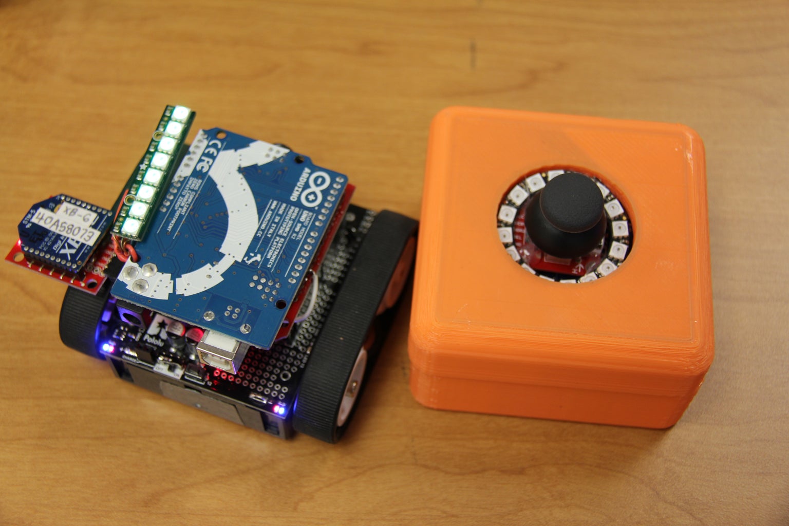
The Qtechknow Robot Obstacle uses the FuzzBot Design, with the Pololu ZumoBot Chassis Kit, SparkFun NFC Shield, XBee Series 1 Wireless Modules, and Adafruit NeoPixel Sticks and Rings. There are 3 main parts of the Obstacle Course:
- The Hacked FuzzBot, with an XBee Module, NeoPixel Stick, and hacked NFC shield
- The Controller, with an XBee Module, NeoPixel Ring, and Joystick
- NFC Tags, placed around the obstacle course
The Robot Obstacle Course has been featured at many Maker Faires - SLO Mini Maker Faire, Maker Faire Bay Area, and the White House Maker Faire! It has won Editor's Choice twice at the the Bay Area Maker Faire, and has the Maker of Merit award at the White House Maker Faire!
Here is the timeline of the complete project, from first prototype to completed project:
Mini Maker Faire SLO: Instead of RFID, I had plates (real dinner plates!) with a force sensor underneath (to detect the presence of a robot above!) with long wires that connected to a central Arduino. Problem: Force sensors didn't work, robot would get stuck on the side of the plates, and XBee communication didn't work
Maker Faire Bay Area: Added RFID which solved the problem of the the plates, and added a few more lines of code to work with the XBees. Problem: RFID didn't consistently read all of the time, because 1) RFID antennae was too far away from the tags and 2) I didn't know, but the RFID Serial pins were connected to the motor pins!
Maker Faire White House: Cut the RFID shield in two, and put the antennae at the bottom of the bot, made the box shorter, and rewired the RFID UART pins. Works perfect now!
Let's get started!
Step 1: Parts and Tools
* All parts are from SparkFun Electronics, except for the ZumoBot Kits / Motors, which are available at Pololu, and the rechargeable batteries, which are available at Amazon.
All tools used in this project are easily reuseable in many other projects, and a majority of the more expensive parts can be reused again in other projects (i.e. Arduinos, XBees, XBee Explorer Regulated).
A SparkFun wishlist that includes all parts except the ZumoBot Kits / Motors, is available here:https://www.sparkfun.com/wish_lists/90202 ($189)
A SparkFun wishlist that includes all tools except the Rechargeable Batteries, is available here:https://www.sparkfun.com/wish_lists/90204 ($42)
Parts for Robot:
- Arduino UNO R3 SMD ($30)
- ZumoBot Chassis Kit ($43 unassembled) + 2 x 75:1 HP Gear Motors ($16 each) // or // ZumoBot Assembled ($100)
- NeoPixel Stick - 8 x LEDs ($6)
- SparkFun NFC Shield ($20) with NFC Module ($30)
- XBee Series 1 Module - Trace / PCB Antennae (802.15.4) ($23)
- XBee Explorer Regulated ($10)
- Stackable Header Kit ($1.50)
- 6 - Pin Right Angle Female Header ($1)
- Right Angle Male Headers ($2)
- Female Headers ($1.50)
Parts for Controller:
- Arduino UNO R3 SMD ($30)
- NeoPixel Ring - 16 x LEDs ($10)
- Joystick ($4)
- Joystick Breakout Board ($2)
- SparkFun XBee Shield ($25)
- XBee Series 1 Module - Trace / PCB Antennae (802.15.4) ($23)
- 3D Printed Enclosure (make your own or print at Shapeways)
Parts for Obstacle Course:
- 15 x NFC Tags (MiFare 1K, 13.56 MHz) ($3 each)
Tools:
- Tool Kit - Beginner** ($22, includes soldering iron and basic tools to complete this project)
- Rechargeable AA Batteries ($22, Amazon)
- SparkFun Cerberus USB Cable ($6)
- XBee Explorer USB ($25)
** solder at your own risk
Step 2: Assembling the Chassis Kit

To assemble your ZumoBot chassis kit, download the PDF below. This is Pololu's instructional guide and it's a PDF so that you can easily read it on your tablet or smartphone! However, if you would like to have more pictures to help you along the way, in the next few steps I'll show you how to make the main chassis!
Take out all of your parts and tools, which were shown in the last step. Here is what is included in the ZumoBot Chassis:
- two silicone tracks
- two drive and two idler sprockets
- a 1/16″ acrylic mounting plate
- battery sockets
- mounting hardware
And here is what is in the Zumo Shield Kit:
- Zumo Shield PCB
- Jumper Connectors (4)
- Jumper Wires for Motors (3)
- Pushbuttons (2)
- Right Angle Switch
- Male Headers (40)
- Female Headers (2)
- Mounting Plates (2)
- Screws for Mounting Plates (2)
You will need the tools from the last step also.
Attachments

Step 3: Soldering the Zumo Shield


Take out the Zumo Shield PCB and all of the electronic components (switch, buttons, headers, etc.) that go with it. Plug in your soldering iron, and if you have a variable temperature iron, set the temperature to be between 350C - 400C (660F - 750F). Grab a small length of your solder (hopefully lead free!!!), and put the Zumo Shield into a vice or third hand.
If you don't know how to solder, that's okay! Head over to this awesome tutorial to learn!
- Put the two pushbuttons into the corresponding holes, and flip the PCB over.
- Solder the four total copper holes.
- Snip the leads with your diagonal cutters.
- Put the switch on the PCB into the copper holes corresponding, and flip the PCB over.
- Solder the three copper holes.
- Snip the leads with your diagonal cutters.
- Put the buzzer into the copper holes corresponding, and flip the PCB over.
- Solder the buzzer total copper holes.
- Snip the leads with your diagonal cutters.
- Using your pliers, snip off one 10 pin male header, 8 pin male headers (2), and one 6 pin male header from the male header strip. Now, put the male headers into the Arduino Leonardo pin headers.
- Flip the Arduino Leonardo over, and put it into the Zumo Shield PCB (the pins that the Arduino Leonardo go into are outlined with a white line).
- Flip the whole package (Leonardo & Zumo Shield) over, and solder all of the copper holes with a male header sticking out of it.
- Snip all of the leads with your diagonal cutters.
- Take the Arduino Leonardo off of the Zumo Shield PCB, and you should see that the male headers (now soldered on!!!) are aligned well.
- Using your pliers, snip off one 4 pin male header, one 3 pin male header, and one 2 pin male header from the male header strip.
- Put these male header segments into the jumper holes (in the middle of the PCB). These will let us select if we want the onboard buzzer, battery monitor, and 3-axis compass to be connected to the Arduino or not.
- Flip the PCB over, and solder the copper holes.
- Snip the leads with your diagonal cutters.
Yay!!! You are now done with the through-hole soldering needed to complete the chassis. Head on over to the next step to find out how to arrange the motors in the chassis!
Step 4: Arranging the Motors


Next, we're going to arrange the motors, so that our Arduino can control them. You'll need to use your soldering iron just a small bit.
- First, get the battery holder out. It's the black box that looks like it can hold 4xAAs.
- Take two jumper wires out of the paper wrapping.
- Cut them both in half with your diagonal cutters.
- Next, bend the one end of each small wire segment into a loop, but don't close the loop.
- Wrap the loop of the wire around the leads of the 100:1 micro metal gear motors.
- Solder the junction between a jumper wire and the motor lead. Repeat the process four times, for the four joints.
- Place each motor into the battery holder, aligned like the picture above. Make sure that the positive side is always outwards. You can tell what side is the + by looking at the black plastic on the motor casing.
- Bend the leads upwards, once you know that the motors are aligned properly.
- Take the two smaller mounting plates out (NOT the full size plate), and take the paper covering off of the acrylic (on both sides).
- First, put the smaller one up towards the motors.
- Next, put the larger one down below the smaller one. These should line up perfectly.
- To test if you got the orientation correct, try putting the Zumo Shield on top of them. The through-hole soldering joints from before should perfectly fit into the mounting plates.
- Put the Zumo Shield on top of the motors, face up. You shouldn't have to bend the motor leads too much, to fit it into the copper holes.
- Make sure that the mounting plates line up with the shield, and then solder them.
- If you haven't found that you made any mistakes (make sure the mounting plates are aligned correctly!), snip the leads with your diagonal cutters.
Now you are finished with arranging the motors! The chassis should now start to look like a robot a little!!!
Step 5: Screws and Nuts

Next, we need to put some screws and nuts to make our FuzzBot complete. Here are the steps:
- Take the two small (the smallest) nuts, and flip the ZumoBot Chassis over. Insert the nut into the hole on the outside of the battery pack on the bottom
- Next, insert a large (the largest) screw into the top of the Zumo Shield, lined up with the nut on the bottom.
- Using a small Phillips screwdriver, screw the screw into the nut, on the bottom.
- Repeat the same process to the other hole on the other side.
- Next, unscrew the large (largest) nut from the idler sprocket.
- Bend the PCB up just a little, and drop the nut into the holder, where the wheel will go.
- Repeat this process twice, for both sides.
- Open up the battery case.
- Take another two small nuts (again, the smallest) and put them into the two holes in the battery case (the ones that actually go through)
- Put two small (smallest) screws into the two holes, on the other side.
- Using a small Phillips screwdriver, screw the screw into the nut, on the bottom. You may want to hold the nuts in with your two fingers.
Almost there!!! All you need to do is add on the wheels to finish your ZumoBot Chassis for Arduino.
Step 6: The Wheels

Yay!!!!! The wheels are finally here! Use these steps to put the wheels and tracks on your ZumoBot Chassis.
- Separate the wheels from each other.
- Next, put a circular hole wheel, then a washer on the idler sprocket.
- Thumb-tighten each idler sprocket onto the large nut, already in the wheel mounting hole at the back.
- With your 3mm Allen Wrench/hex screw, tighten the idler sprocket on the nut. Make SURE that you do not tighten the idler sprocket too much, for doing this can cause the washer to bend.
- To the same to both sides.
- Take out the half-circle wheels.
- Make sure that the Pololu logo is facing outwards, and then press down on a table to level the wheel. Do the same on both sides.
- Add the tracks to both sides.
You are now finished making the ZumoBot Chassis Kit for Arduino!!!
Step 7: Soldering the Shield


Take out the RFID Shield from SparkFun and solder on the four stackable headers onto the shield. Next, solder on the female 6 - pin right angle header onto the XBee Socket, but with the header facing the opposite way than in the picture. Solder a 6 pin right angle male header to the XBee Explorer Breakout, and plug into the header. The XBee Explorer Breakout should be upside - down and to the right, hanging off of the shield.
Next, solder on two 14 pin female headers onto the RFID Module socket, and plug in the RFID Module. Go ahead and load the example code onto an Arduino with both the RFID Module and XBee Explorer plugged into the shield, and make sure everything works well.
Photo Credits: SparkFun Electronics
Step 8: Hacking the Shield


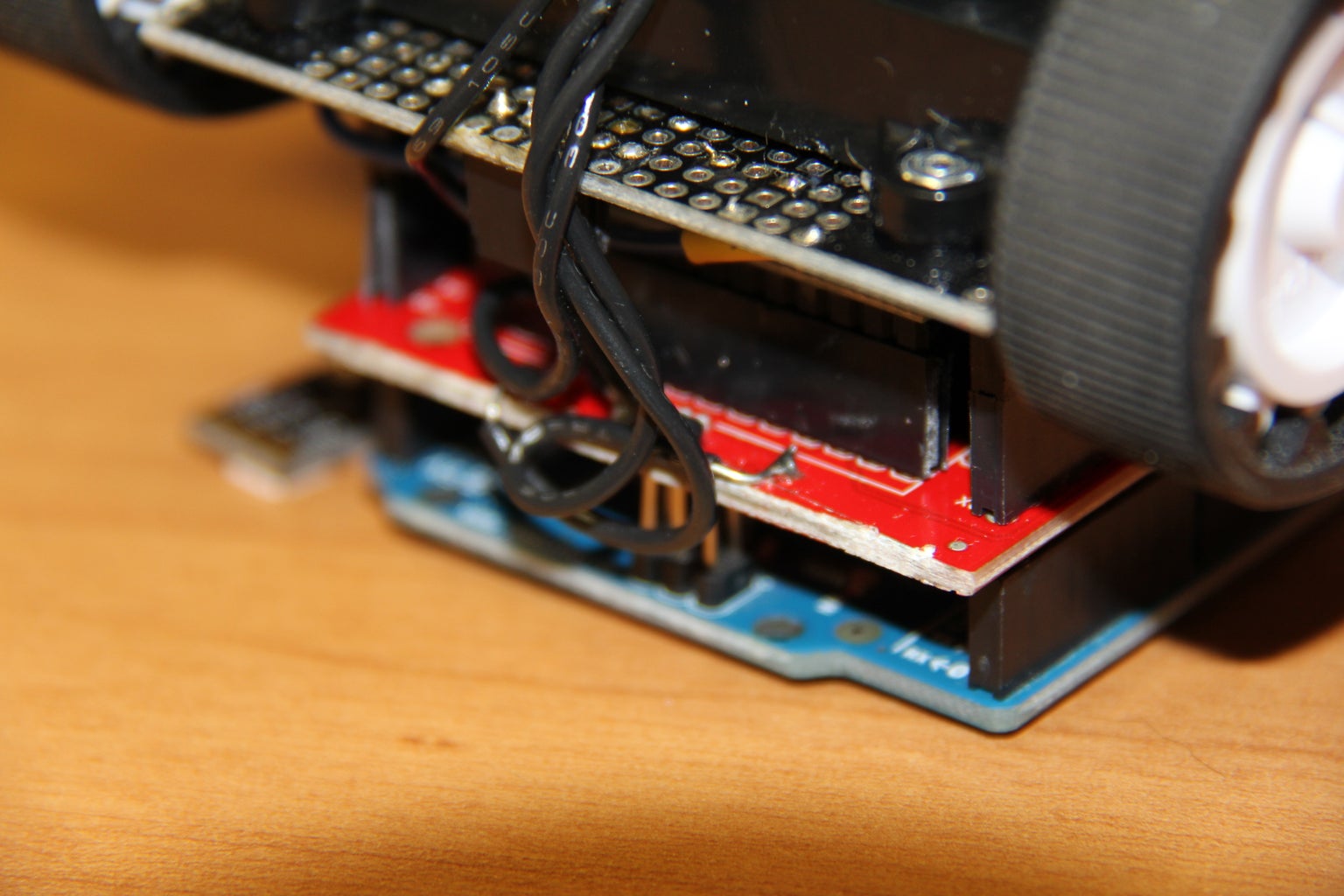
Once you have the shield all of the way soldered / assembled, we'll start hacking the shield so that we can move the antennae to the bottom of the robot! This will require you split the shield, and we'll shave off the solder mask from the board, so we can get to the copper for the antennae.
First, take a X-ACTO knife and start cutting the shield, right at the junction of the tiny capacitors, and the main antennae (in-between the mounting holes and the capacitors). Eventually, the shield will snap.
Next, take your diagonal cutters and firmly rub the tip to the board (on the backside, right next to the vias), on the three copper wires. After the copper traces are exposed, add a little solder to each trace. Carefully, place a wire parallel to the trace, and solder (repeat for every trace). Desolder the two 0 ohm resistor on the top of the shield (it should be very easy), and scratch off the solder mask next to the capacitor group. Add a little solder between the three closest pins of the capacitors to each group. Next, solder the middle trace (on the back of the antennae) to the copper next to the capacitor group, solder the closest trace on the antennae to the bottom capacitor bank, and the farthest trace on the antennae to the top capacitor bank. Scratch off part of the top of the left wing of the antennae, and solder a wire from there to the spot next to the capacitor group (where you soldered the middle trace on the back to), and to the same to the right wing.
Carefully, put hot glue over the exposed copper on the bottom and top of the shield, to make sure nothing shorts out or breaks apart.
You have now completed hacking the RFID Shield!
Step 9: Adding the Neopixels


The NeoPixel Stick that you have is based off of the WS8211 chipset, which basically means that you the LED's have tiny chips inside that make them each individually addressable, with only one pin (whereas without the WS8211 in the NeoPixels, you would need one pin per LED). They also can each make millions of different colors by mixing red, green, and blue!
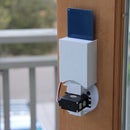
Take out some wire, and cut 2 pieces down to about 3 - 4 in. in length + one 5 - 6 in. length, and solder one end of each wire to GND, DIN (make sure that you don't solder to the DOUT side of the Neopixels, and that you solder the long wire to this pin!), and 4-7VDC. Take one wire, and cut it about 3 - 4 in., but don't strip the ends. Wrap the wire around the ends of the three wires that you soldered to the NeoPixel Stick (but make sure that the wires don't short together!), and then through the bottom left mounting hole of the Arduino UNO (since it is upside down, it will be the lower right mounting hole), finally twist the wire so that it the NeoPixel Stick is snug around the mounting hole. Then, bend the NeoPixel Stick 90 degrees down, so that it is flush with the PCB of the Arduino UNO (see pictures).
While you have your soldering iron on, take each of the ends of the wires that you soldered to the NeoPixel Stick, and find which wires are which. The GND wire should be soldered to GND on the ZumoBot shield, 4-7VDC soldered to 5V, and DIN all the way to D5, which is on the far side of the front panel that has the I / O pins broken out to
Step 10: Controller Box Soldering


Take out the XBee Shield from SparkFun, Joystick, Joystick Breakout, NeoPixel Ring, a 6 pin female header, a 6 pin male header, and some wire. First, solder the 6 Pin male header to the Joystick Breakout, and the 6 pin female header into the shield, so that the joystick is in the exact center (it should be the very edge of the prototyping area), and solder these pins on the female header to the Arduino pins:
Joystick VERT -> Arduino A0
Joystick HORZ -> Arduino A1
Joystick VCC -> Arduino 5V
Joystick GND -> Arduino GND
Next, solder wires to each pin (except for DOUT) of the NeoPixel Ring (make them about 2-3 inches long), and connect them to these pins on the Arduino:
DIN -> D4
VCC -> 5V
GND -> GND
On the XBee Shield, make sure that the switch is switched to the UART side.
Step 11: Making the Controller Box
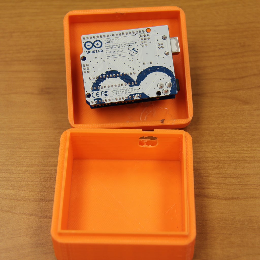
Print the Qtechknow Robot Obstacle Course Controller enclosure off of Thingiverse here. It's a normal box with a hole in the side for power for the Arduino, and a hole in the top for space for the NeoPixel Ring and Joystick. Print in PLA, or ABS, in whatever color you would like.
Next, put the soldered controller box into the enclosure, with the NeoPixel Ring being inside the hole at the top and the joystick in the middle of it, and hot glue in place. Close the enclosure, and then you are finished!
Step 12: XBee Configuration


Download a Serial Terminal Program if you haven't already: CoolTerm for Mac, Windows, Linux
In this step, we will configure the XBee for the Controller, and the Robot. Take a look at the back of your controller XBee (either one), the bottom 8 digit / letter string, and that will be your 'a' variable. Next, take a look at your Robot XBee, and the bottom 8 digit / letter string, and that will be your 'b' variable.
Type this in the serial monitor, once you have attached the XBee Explorer with your Robot XBee in, and the /dev/tty.usbmodem... serial port (and wait for it to say OK, before you type in the next line):
+++
ATID 7682
ATDH 13A200
ATDL a
ATWR
And type this into the serial monitor once you have plugged in the Controller XBee in:
+++
ATID 7682
ATDH 13A200
ATDL b
ATWR
Step 13: Coding

Upload the code below to each Arduino:
Controller: QTKobstacleController.ino
Robot: QTKobstacleRobot.ino
Make sure that you have uploaded the correct code to each Arduino, using the settings of "Arduino UNO", and the correct COM / Serial Port. Also, before uploading, remove both XBees from each board, and when uploaded, plug them back in.

Step 14: Finished!

Congratulations! You have completed your very own Qtechknow Robot Obstacle Course! Play against your friends with two robots / controllers, or play for the world record of 24 points in 30 seconds (set at the Maker Faire White House)!
Please post a picture in the comments of your Qtechknow Robot Obstacle Course once you have made one, and especially if you have beaten the world record!
Also, please vote for me in the RC Contest, Tech Contest, and Microcontroller Contest if you liked this Instructable / project!

Participated in the
Tech Contest

Participated in the
Microcontroller Contest

Participated in the
Remote Control Contest


