

Introduction: Quiz Game Buzzers (Arduino / RGB / I²C )


Quiz Games are fun and they get even better when you've got the right equipment.
I needed some Game Buzzers for a birthday party but everything I could find was either too expensive or not versatile enough so I came up with these. Here's what features I needed my Buzzers to have so you can decide whether they can suit your case too:
- easy to make (basic soldering skills, standard tools)
- cheap and readily available components (everything in there is standard stuff)
- scalable (1 Buzzer? 2 Groups? 5 Teams? doesn't matter)
- universal (15 Addressable RGB LEDs for team-colors and animations)
- I²C capable (Hook up all Buzzers to a single BUS-Line)
- re-programmable (ICSP Port on the bottom for quick software updates)
Here we go...
Step 1: What You Need

Material for one Buzzer
- 1 WS2812b RGB LED Strip with 15 LEDs (cut to 14 + 1)
- 1 Atmel ATTiny85 µController (SOIC SMD if you want to use the provided board layout or PDIP package if you go for the no-PCB-Frankenstein version)
- 1 Electrolytic Capacitor 100µF/16V or equal (just for smoothing the power line)
- 2 Resistors: 1x 150Ω, 1x 10kΩ
- 1 6pin Encased Header (ICSP)
- 1 Etched PCB (or equivalent circuit setup)
- 3 Momentary Switch 8x8mm (NC, normally closed)
- 2 10cm Strip of flat ribbon data cable (3 pole)
- 1 20cm single pole wire (I used some leftover strands from the ribbon cable)
- 1 translucent plastic hemisphere (10cm diameter)(I got mine from a wedding supply store)
- 1 3mm plastic disk (10cm diameter)(preferably flexible and easy to cut e.g. guttagliss hobbycolor, you can also use plywood)
- 1 2cm piece of plastic conduit (1cmx1cm) or equivalent piece of plastic
- 1 piece of cable for connecting the Buzzer (4 pole)(I recommend LIYY 4x0,14mm² as it's thin and flexible)
Tools
- Hot Glue (tons of Hot Glue)
- Soldering Iron / Solder / Flux
- Cutter / Scissors
- Sandpaper
- Electric Drill and drill bits (10mm, 3mm)
- Handsaw
Step 2: Soldering the PCB


The PCB has a quite simple layout and will assist you during assembly by providing a central anchoring point for all the components. Therefore I really recommend etching your own PCBs for this, especially if you aim for more than 2 Buzzers. You can of course always just build the circuit Frankenstein-style from the schematics as it is fairly simple.
PCB Layout was created with Fritzing: fritzing.org
Things worth noting
Yes the capacitor is mounted on the "wrong" side of the PCB. This is actually intended. There is also a wire jumper on the backside of the board. don't forget to put it in.
Before going on
Make sure the boards are working correctly by burning the boot-loader to the µController. You can find all necessary instructions on how to set up your Arduino IDE for ATTiny here: highlowtech.org: ATTiny Hardware Support for Arduino IDE
You can use your Arduino as an In-System programmer by uploading the example sketch "ArduinoISP"
Burning the boot-loader will make sure your board is wired correctly and no traces are broken. It will also set various fuses inside the blank ATTiny so it can later be programmed with your actual software. Without the boot-loader your ATTiny will not start.

Step 3: Preparing the Case


Bowl
Use some fine sanding paper to rough up the inside of the plastic bowl. This will help distribute the light more evenly. Wet sanding will result in a more smooth look.
Drill a 3mm hole (or bigger. depending on the cable you want to use) into the Side of the hemisphere
Base
Cut a round piece of plastic that fits inside the bowl. Make 3 more holes (10mm) for the switches and one square cutout for the programming connector. Use the PCB as a reference for alignment of the hole so the board is roughly centered.
Step 4: Switches


We only need the normally closed switch so you can break off the middle leads (when in doubt measure the switch using the continuity function of a multimeter) Bend the remaining leads over and solder them together. This will parallel the switches inside and give the circuit some mechanical stability as now both contacts have to trigger to break the circuit.
Push the switches through the holes and secure them and the PCB with some hot-glue. Use only one large blob of hot-glue in the middle of the board. This will make wiring easier.
Step 5: Wiring the Push-Button Loop


All switches are connected in series so wiring is straight forward. Go from the GND pad through each switch and back to the boards button input pad. After soldering is completed you can hide the wires underneath the board so they don't get in the way. Apply some more hot-glue on top of the switches to give them more stability as this is the point where the "200 pound gorilla" is interfacing with your buzzers as AvE would put it.
Step 6: Wiring the LEDs (1)


Wiring the LED strips is a little complex so please read carefully and have a look at the pictures when in doubt.
Take the 14 LED strip and solder one 10cm piece of 3 pole wire to the INPUT side facing away from the strip. Now flip the strip over and solder another 10cm piece of wire to the OUTPUT side but this time the wires are soldered to the back of the strip and facing towards the strip.
Step 7: Wiring the LEDs (2)


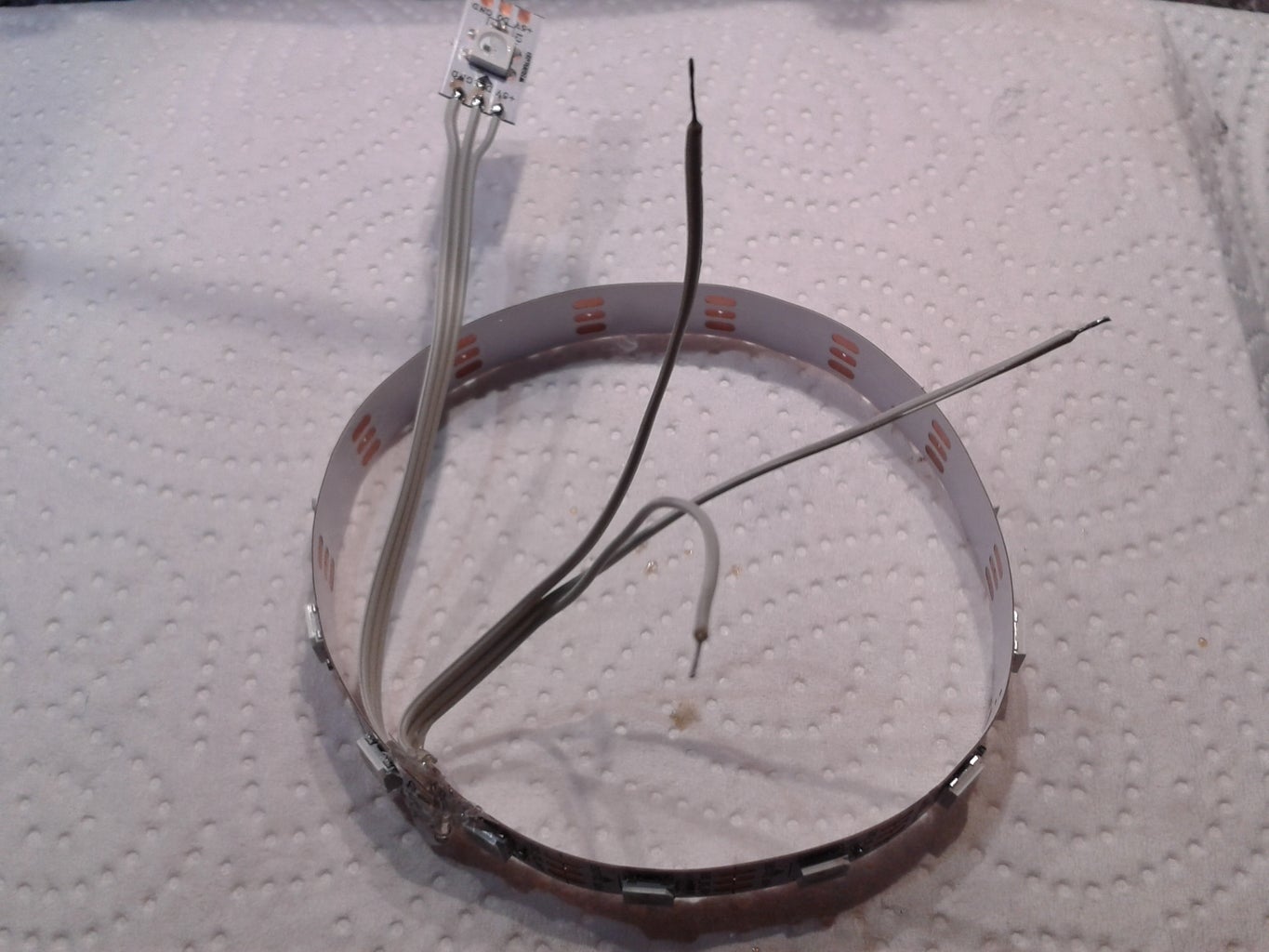
Now we need to insulate the solder joints. Glue a piece of plastic foil over the INPUT side of the strip using hot-glue. You can now bend the strip into a ring shape and glue the OUTPUT side on top of the insulating foil. After that you will end up with an LED ring and all wires sticking out on the inside of the ring. The last step of connecting the LEDs is to solder the remaining single LEDs INPUT to the OUTPUT side of the ring. At this point you need to make sure you don't mix up inputs and outputs or the polarity of the strips (GND / +5V). Using color coded wire helps a lot ;)
Step 8: Joining the Mess


Complete the wiring by soldering the 4 pole data/power cable to the respective pads on the PCB (make sure to take note which wire goes where) and connect the LED ring to the GND / VCC pad and its INPUT to the remaining digital pin pad next to the formerly connected button-loop pad.
Step 9: Almost Done


For a finishing touch Glue the LED ring on top of the switches using (you guessed it) more hot-glue. Then use a bit of plastic (I used a piece of 1x1cm plastic conduit) as a spacer to put the single LED in the middle near the top of the plastic bowl. Make sure everything that might come lose is properly glued in place as these buzzers are likely to get smashed pretty hard.
Finally slide the bowl over the cable and push the base inside. You can secure it with a cable tie or a few dots of hot-glue underneath. Don't overdo it here as you might want to be able to replace broken covers in the future.
And you are done with the hardware part.
Step 10: Software

Ideas
The buzzers are extremely versatile as they contain their own controller. You basically just have to provide 5V DC to them and program whatever you like them to do. The two remaining wires of the 4 pole cable are just connected to 2 of the controllers digital pins so you can use them for software serial, software I²C or even just as regular I/O pins. That means even with just 2 buzzers and one additional switch for the "game-master" you'd be able to program a two-player game (One data line for the "buzzer pressed" signal and the other one for "reset").
Testing
To first of all make sure everything is working fine you can upload "buzzer_firmware.ino" to your buzzers. This sketch will put the buzzers into test mode when powered up. Every press on the buzzer will result in iterating through RGB base colors on every single LED (RED -> GREEN -> BLUE -> WHITE). Make sure to set the #defines of LED_COUNT and I2C_SLAVE_ADDR according to your configuration.
You also need the following libraries:
Adafruit NeoPixel (WS2812b) https://github.com/adafruit/Adafruit_NeoPixel
TinyWire I²C for ATTiny https://github.com/rambo/TinyWire/tree/master/Tin...
Don't forget to also include the "WS2812_Definitions.h" Header file into your sketch directory as it is needed by the NeoPixel Library.
Going Further
For a multi-player setup with even more buzzers you can use the provided Arduino sketches and wire your buzzers as shown in the first picture. The Arduino UNO acts as a polling server that checks the Buzzers via I²C for button presses and translates messages received on its serial connection to the I²C BUS-network (Use buzzer addresses 30 - 39 or change the Code in "buzzer_Serial_I2C.ino" accordingly).
Refer to "Commands.md" for a quick guide on what command structure to use and send some messages to your buzzer network using a serial terminal.
For example sending
30:mode.3
30:tcolor.0xFF8C00
will set the buzzer with address 30 to animation mode 3 and then change its team-color to darkorange. Have a look at "WS2812_Definitions.h" for more standard colors.
Ultimate Party
So now that we got a network of buzzers connected to our PC what to do with it? I also wrote a Java application for managing multiple teams and 2 games in the style of "Beat the Star" that interfaces directly with the Arduino UNO via Serial.
Visit my github Account for more information and downloads of the software:
https://github.com/simonthechipmunk/buzzworks
Happy buzzer smashing!


Participated in the
First Time Authors Contest 2016


