

Introduction: REMIX - Simple Arduino Keypad


This is a REMIX of gtr_stitch's Arduino Keypad. This is a simple keypad to use for just a few buttons There are Arduino libraries available for using an actual keypad. I made a few modifications of the original author's project. I omitted the LCD and only used 4 button switches.
I aim to use this as a lock interface for a gun cabinet.
Step 1: Gather Your Supplies
For this Instructable, I used:
Arduino Uno R3
a larger breadboard
a basic servo
4 momentary tactile switches
2 LEDs, one red and one green
6 330Ohm resistors
various lengths of jumper wires
Computer with Arduino IDE 1.0.5 and an appropriate USB cable
Step 2: Wire in the Buttons

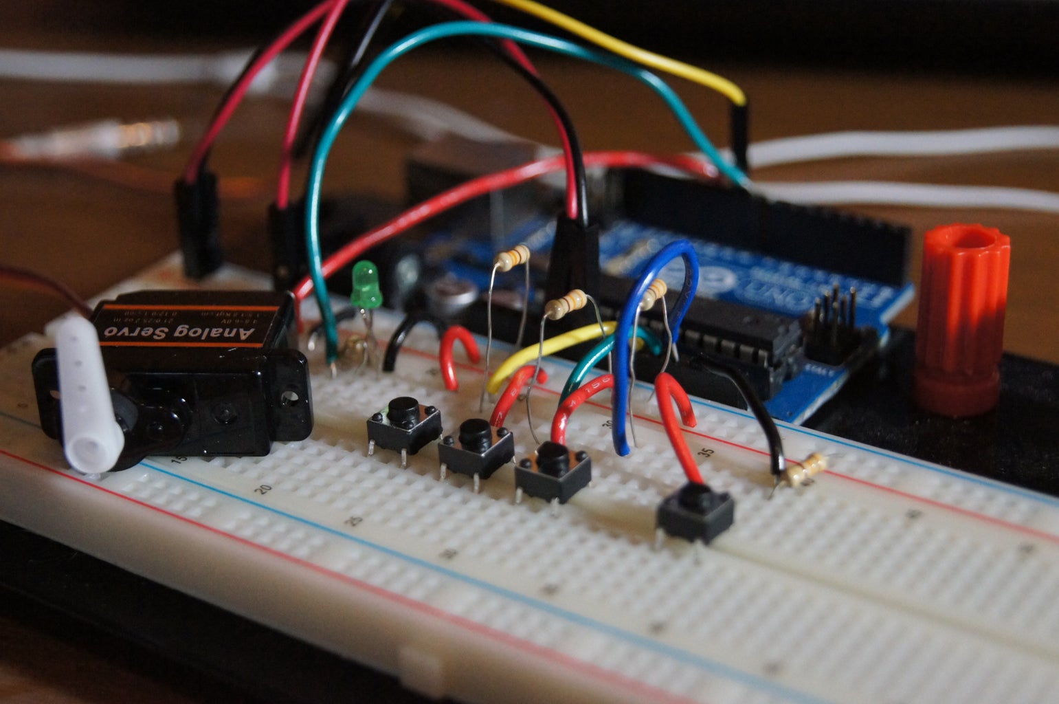
I have the power rails of the breadboard wired to the 5V and GND on the Arduino.
The tactile switches are placed across the gap of the breadboard. One side of the switch is tied to the 5V rail, the other goes to the Analog pins, A0-A3 respectively, with a 330 Ohm resistor tied to GND.
Step 3: Wire in the Servo

The Servo I have pinned to 5V and GND on the breadboard rail. The data line I have to pin 9 on the Arduino.
Step 4: Wiring in the LEDs

I have a green LED for an access granted indicator and a red LED for an access denied indicator. I have the positive of the green LED pinned to Arduino pin 8 and the ground of the green LED pinned to ground along with a 330Ohm resistor. The red LED is tied on the positive end to Arduino pin 10 and the ground is wired the same as the green, to GND with a 330Ohm resistor.
Step 5: Coding

This code should be able to be copied and pasted into the Arduino IDE.
Basically, after we set everything up, the arduino reads which button was pressed, how many times, and, if the total presses equals a certain amount, compiles the data to match a predetermined number of presses for each button.
I will save you my attempt to explain this and direct you to gtr_stitch'skeypad as he does a great job explaining the programing.
In the code, you can change how many presses each button must receive in order to activate the servo. Likewise, you can change the delay the lock waits after receiving an incorrect combination or time the servo stays activated.
If you find anything unclear, please leave a comment and I'll try my best to explain.
#include <Servo.h>
Servo MyServo;
const int button1 = A0;
const int button2 = A1;
const int button3 = A2;
const int button4 = A3;
//keeps track of how many times button is pressed
int count1 = 0;
int count2 = 0;
int count3 = 0;
int count4 = 0;
//keeps track of state of button
int state1 = 0;
int state2 = 0;
int state3 = 0;
int state4 = 0;
//keeps track of previous state
int prev1 = 0;
int prev2 = 0;
int prev3 = 0;
int prev4 = 0;
// totalcount is how many times button was pressed
int totalcount = 0;
// declare the LEDS
int green = 8;
int red = 10;
void setup(){
pinMode (button1, INPUT);
pinMode (button2, INPUT);
pinMode (button3, INPUT);
pinMode (button4, INPUT);
pinMode (green, OUTPUT);
pinMode (red, OUTPUT);
Serial.begin(9600);
MyServo.attach(9);
MyServo.write(0);
for (int i = 0; i<180; i++){
MyServo.write(i);
delay(50);
}
MyServo.write(0);
}
void loop(){
state1 = digitalRead(button1);
state2 = digitalRead(button2);
state3 = digitalRead(button3);
state4 = digitalRead(button4);
if (state1 != prev1){
delay(10);
if (state1 == HIGH){
count1 ++;
}
}
if (state2 != prev2){
delay(10);
if (state2 == HIGH){
count2 ++;
}
}
if (state3 != prev3){
delay(10);
if (state3 == HIGH){
count3 ++;
}
}
if (state4 != prev4){
delay(10);
if (state4 == HIGH){
count4 ++;
}
}
prev1 = state1;
prev2 = state2;
prev3 = state3;
prev4 = state4;
totalcount = count1 + count2 + count3 + count4;
if (totalcount == 4){
if(count1 == 1 && count2 ==0 && count3 == 1 && count4 == 2){
Serial.println("CODE ACCEPTED");
MyServo.write(90);
digitalWrite(green, HIGH);
digitalWrite(red, LOW);
count1 = 0;
count2 = 0;
count3 = 0;
count4 = 0;
totalcount = 0;
delay(10000);
Serial.println();
MyServo.write(0);
digitalWrite(green, LOW);
}
else {
if (count1 !=1 && count2 !=0 && count3 !=1 && count4 !=2 && totalcount == 4){
Serial.println ("CODE REJECED");
digitalWrite (red, HIGH);
digitalWrite (green, LOW);
count1 = 0;
count2 = 0;
count3 - 0;
count4 = 0;
totalcount = 0;
delay(5000);
Serial.println("ENTER CODE");
digitalWrite( red, LOW);
}
else if (count1 > 1 && count2 >0 && count3 >1 && count4 >2 || totalcount == 4){
Serial.println("CODE REJECTED");
digitalWrite(red, HIGH);
digitalWrite(green, LOW);
count1 = 0;
count2 = 0;
count3 = 0;
count4 = 0;
totalcount = 0;
delay(5000);
Serial.println("ENTER CODE");
digitalWrite (red, LOW);
}
}
}
}
Step 6: Test and Debug
Luckily, the Arduino IDE has that handy 'verify' button to alert me of my typos. Once that is straightened out, upload your code to the arduino and test it out. I had some syntax issues that, after some sleep(mostly this) and revision, seemed to resolve themselves. If it doesn't work the way you want it to, don't give up! keep at it!
This will make a great lock for deadbolts, such as on a cabinet.
Again, if you have any issues just leave a comment and I'll help to the best of my abilities.
If you like this Instructable, vote for it in the REMIX contest.
Thank you.

Participated in the
Tech Contest

Participated in the
Remix Contest

Participated in the
Microcontroller Contest


