

Introduction: RFID Access Control With Arduino Yun and Raspberry Pi
Welcome to my Instructable! Have you searched online for an RFID Access Control System that can have multiple users without using a master key to program it? A system that can log the access with the persons name? A system where you can easily add or remove someones access easily? Look no further! This system has an easy to use Graphical User Interface through a web browser. This is instructable will walk you through each step on how to build and program this system. I have searched for a tutorial on how to do this when I wanted to build one. I pieced information from different tutorials, forums, and videos until i created my own. The closest I could find to what I wanted was this instructable: https://www.instructables.com/id/Control-Access-of..., but it wasn't everything I wanted to do. I did use the basic wiring from that instructable but improved on it.
Step 1: How It Works
This system uses both and Arduino and a Raspberry Pi. The arduino I chose was the YUN for its ability to have wifi and make it's own network. I chose the Raspberry Pi Zero because of its small form factor and has built in Wifi and has a good price.
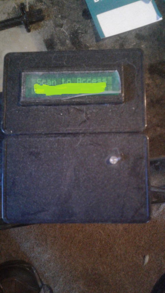
When Arduino starts up it broadcasts its wifi and starts all the connections. It reads the Real Time Clock (RTC) and sets it to the system time. The LCD screen displays a welcome message. The Raspberry Pi connects to the wifi network the YUN broadcasts. When you scan the RFID card, the arduino will read each byte and create a string of hexadecimal numbers, it starts a python script to compare that string to a field in a MySQL table on the Raspberry Pi. If it matches it flashes a green LED, displays Access Granted on the LCD, sends a signal to open a door strike to open the door, starts a python script to log the RFID code, the date and time, and Granted Access to another MySQL table, flashes a blue LED, displays Logging on the LCD screen, then displays the welcome message again. When the RFID code does not match, the LED will flash red, the LCD screen will display Access Denied, flash the blue LED, Logs the data, and display the welcome message again.
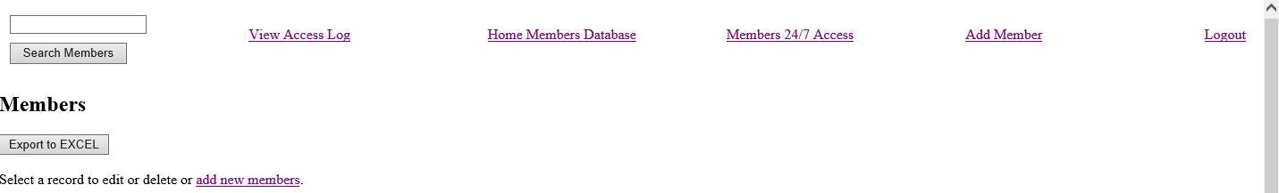
The Webserver is how you add or remove users, edit their information, and view the access log. PHP will fill in the users name with the matching RFID code in the access log. You can also export both the Access Log and the Users Database to a CSV file viewable in a spreadsheet. The Access Log will purge anything older than 60 days.
Step 2: Parts


Arduino Yun
Raspberry Pi Zero W
Micro SD Cards - a 2 GB for the YUN and a 32GB for the Raspberry Pi
Innovations ID-20 RFID reader
Breakout Board for RFID reader
16X2 Character LCD Screen
Serial Backpack for the LCD Screen
RGB LED
DS3231 RTC - Only needed if this will not connect to the internet
Buzzer
Jumper Wire
Headers and pins
125KHz RFID Cards
12V Access Control Power Supply
DC Relay that can be controlled with 5V DC and pass 12V DC - I used a solid state relay
12V car plug cigarrette lighter style socket
12V USB car charger with 2 USB Ports with at least 2 amps power
12V Electric Door Strike
Plastic case - large enough to house reader and LCD Screen
10" X 10" X 4" electrical box to house the components.
2 modular ethernet plugs (female) with punch down ability
an ethernet cable
a small prototype PCB Board (the ones with holes and copper rings around the holes to make your own PCB.)
Some 16 gauge wire
2 micro USB cables
Length of 2 wire lamp cord (long enough to go from door strike to Main Box)
Step 3: Assemble the Reader Box and Components


We will first prepare the reader. Solder 90 degree pin headers to the RFID Breakout board, Then solder the breakout board to the RFID reader and put aside.
We will next prepare the LCD screen by soldering the pins of the serial backpack to the LCD screen PCB. Once all the pins are soldered on, cut the excell pins sticking up to high with diagonal cutters. Place the LCD screen to the side.
Cut a square piece of PCB so it has 2 rows of holes by 6. Take 2 6 pin headers and solder to the PCB board. Connect the solder joints the long way along the pins to create 2 solder lines but keep the 2 lines separated. This will by our junction for all the 5 volt and the ground needed in the reader box.
The RGB LED will have 4 leads, so cut another piece of PCB board with 4 holes by 2 holes. Solder the 4 leads to the board and bent the LED 90 degees to be inline with the board. Solder a 4 pin header on the remaining side of the PCB and connect each pin to a lead of the LED with solder making 4 small rows. This will take a steady hand and maybe a few tries to keep the 4 rows from touching eachother.
Take the plastic box and drill a hole in the back large enough for an ethernet cable to fit into it, Then cut a square hole on the front for the LCD screen, and small hole just smaller then the LED and push the LED snugly into it.
Take jumper wires and connect the following, Write down the colors each component gets punched down to on the Ethernet Modular Jack, The jumper wires will punch down nicely on the back of these.
------------------------------------------------------
1 pin on GND Junction -----> Ethernet punch down (remember which color)
1 pin on 5V Junction --------> Ethernet punch down (remember which color)
-------------------------------------------------------
RFID reader pin out:
PIN 1 ----> GND Junction
PIN 2 ----> 5V Junction
PIN 7 ----> GND Junction
PIN 9 --> Ethernet punch down (remember which color) -------> Eventually to Arduino PIN 10
PIN 10 ---> BUZZER --> GND Junction
PIN 11 ----> 5V Junction
-----------------------------------
Led Pin out
Red ------> Ethernet punch down (remember which color) --------> Eventually to Arduino Pin 9
Green ----> Ethernet punch down (remember which color) --------> Eventually to Arduino Pin 8
Blue ------> Ethernet punch Down (remember which color) --------> Eventually to Arduino Pin 7
GND ------> GND Junction
--------------------------
LCD Screen Pin Out:
RX ---------> Ethernet punch down (remember which color) -------> Eventually to Arduino Pin 11
5V ---------> 5V Junction
GND -------> GND Junction
----------------------------
The buzzer connects to GND Junction (-) and to Pin 10 of the RFID Breakout (+)
----------------------------------------------------------------------------------------
After this, there will be 1 unused punch down. This only requires 7 of the 8 wires of the Ethernet cable.
Slide the ethernet cable through the back hole created and plug into the socket. Use double sided tape along the edge of the LCD screen and press into the front square cut out reader box arrange the components inside the box and close it up.
The reader box is now all set and ready for mounting.
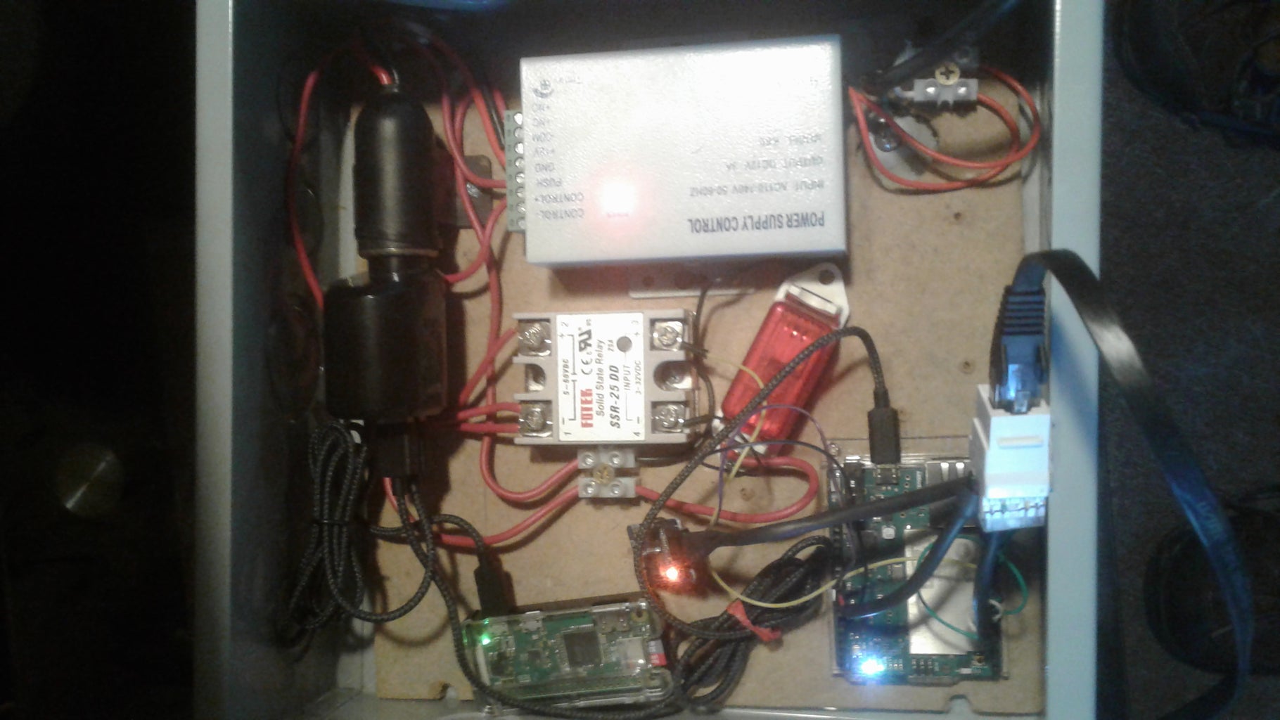
Step 4: Assemble the Main Box
Cut a small piece of plywood that can fit inside the 10 X 10 X 4 Main box and fasten it to the inside of the box by screwing screws through the back of the cabinet into the plywood. The plywood will be the mounting for our components.
Mount the 12v power supply, the Arduino Yun Case, the Raspberry Pi Case, the 12V Socket, and the relay to the plywood. Cut the end of a computer power cord off and strip the 3 wires back. Connect the black and white wire to the 120V in on the 12v Power Supply, and the green directly to the metal case. Knock out one of the holes in the Main Box to run the power cord through.
The 12v Socket will have 2 wires coming off it, a red and a black, strip the ends. The red will go to the +12v terminal on the power supply, the black will go to the COM terminal on the power supply. Cut a length of 16 gauge wire to reach the relay from the power supply and strip both ends. On the 12V side of the relay screw this wire onto the negative terminal and then to GND terminal on the power supply. Cut another length of 16 gauge wire to go from the 12v side of the relay on the positive terminal and to the PUSH terminal on the power supply. Wire the lamp cord, one to the NO terminal on the power supply (Negative on the door strike) and the other to the Positive terminal on the relay (you will now have 2 wires coming off this terminal) (goes to the Positive on the door strike.) You can run this cord through the same knockout as the power cord.
Now use 2 jumper wires and connect from the 5V side of the relay to the Arduino, Positive to Pin 12, Negative to GND.
The RTC has 4 Pins, power, GND, SDA, SCL. Connect 4 jumper wires to these. The power will plug into the 3.3V pin on the Arduino, the GND to a GND pin on the Arduino, the SDA to the SDA pin on the Arduino, and the SCL to the SCL pin on the Arduino.
Now take 7 jumper wires, and punch them down on the back of another ethernet socket, the same colors you used before.
The plug the 5V pin on the Arduino to the color that matches the 5V Junction, and do the same with the GND to the GND and the remaining wires also. Pins 7, 8, and 9 are for the LEDs, Pin 10 for the RFID reader, and Pin 11 for the RX on the LCD Screen. You can run the ethernet cable from the reader box through a knockout on the main box and plug it into the socket you just punched down. Plug in the USB Car charger, and run the Micro USB cables from there to the Raspberry Pi and the Arduino. The Main Box is now assembled. and all the hardware is done.
Step 5: Initial Setup of Arduino YUN
Before powering the YUN, plug in the 2GB MicroSD card.
Setup the YUN using the instructions on the Arduino Site to set-up the YUN to your local network and add a password. Follow the instructions to mount the SD Card.
Using PUTTY log into the YUN with the IP address, ID will be root, and PW.
We will need to install MySQL and Python Connector to be able to access MySQL on the Raspberry Pi type:
opkg install mysql-server opkg
install python-mysql
Now set up the Arduino Yun to act as a wireless access point with the default IP address (192.168.240.1) which is the default.
Step 6: Setup the Raspberry Pi
First you will need to burn the latest copy of Rasbian to a 32GB Micro SD Card. There are plenty of tutorial on how to do that so I will not get into that.
Take the Raspberry Pi and hook up a keyboard, Monitor, and mouse to it. Insert the 32GB SD card and power it up.
Log into with username pi and pw raspberry, you can change that later. Once the screen loads click on the wifi icon and connect it to your home wifi. Write down the IP Adress. Open the console window (black square icon with cursor) and type these commands to update package list and update the software already on the Pi.
sudo apt-get update
sudo apt-get upgrade
sudo raspi-config
Here you will want to expand the file system, enable SSH, and disable the desktop at startup. You can also change your password here now too. restart, log in.
Now we will install remote desktop (this is why we need SSH enabled). In the command line type
sudo apt-get install xrdp
Now you can open remote desktop from your windows computer and type in the Raspberry Pi IP Address and username and password. Keep the keyboard, monitor, and mouse setup tho because we will need to use it later.
We need to add a boot delay to the Raspberry Pi so later when we power the Raspberry Pi and Arduino YUN together, it will allow the YUN wifi to start before the Raspberry Pi. From the console type:
sudo nano /boot/config.txt
Scroll to the bottom and add this line:
boot_delay=75
Press CNTRL X, Y, Enter to Save. This will add a 75 Second Boot Delay. Reboot the Raspberry Pi and verify.
While we are now on your computer now is a good time to install PUTTY and WinSCP to your computer. We will need it to continue. PUTTY is a remote console window for the Raspberry Pi and Arduino YUN later on, and WinSCP is a secure FTP to transfer files from your computer to the Raspberry Pi from your computer.
Step 7: Setup MySQL, PHP, and Python on the Raspberry Pi
From your computer open PUTTY and type in the IP Adress of your Raspberry Pi and log in. We will install MySQL, Type the command:
sudo apt-get install mysql-server
Now to open MySQL Type:
sudo mysql -u root
Now that we are in we need to configure MySQL to work in our application, anywhere I type a word surrounded with & & that is where you will input your data, Keep all ' in the commands and be sure to use ; at the end of the command. Type:
CREATE USER '&user&'@'localhost' IDENTIFIED BY '&password&';
GRANT ALL PRIVILEGES on *.* TO '&user&'@'localhost' WITH GRANT OPTION;
quit;
you created a user name and password with all permissions in MySQL Now log in with your new credentials.
mysql -u &user& -p
It will now ask for your password.
&password&
Now you are in with your username and password. We will now create a database and table:
CREATE DATABASE arduino;
GRANT ALL PRIVILEGES ON arduino.* TO '&user&' IDENTIFIED BY '&password& ' WITH GRANT OPTION;
Use the the same username and password you created for the MySQL log in. Below we will create a table called usersrfid under the database arduino.
USE arduino;
CREATE TABLE usersrfid(id INT(255) NOT NULL AUTO_INCREMENT PRIMARY KEY);
We just needed to create it to add to it later. id is the first column of the table and will be a number that auto increments and each table needs a primary key, so we set this column as the key. Now exit MySQL by typing:
quit;
Now we need to install the webserver, PHP, Python, and all the connectors for MySQL Type the following commands:
sudo apt-get install mysql-client
sudo apt-get install python-mysqldb
sudo apt-get install apache2 php5 libapache2-mod-php5
sudo apt-get install php5-mysqlnd
Next we will install PHPMyAdmin. this will be used to build your MySQL tables without using command line.
sudo apt-get install phpmyadmin
a few options will appear, choose apache2, yes to dbcommon, and enter a password for phpmyadmin.
Now we need to edit apache2.conf to use PHPMyAdmin to do this Type:
sudo nano /etc/apache2/apache2.conf
Scroll to the bottom and type:
Include /etc/phpmyadmin/apache.conf
Then press CNTRL X, Y, then enter to save. Once saved we will need to restart apache2 type:
sudo /etc/init.d/apache2 restart
Now open a web browser in Windows and type in the address bar the IP Address of the raspberry Pi followed with /phpmyadmin and log into PHPMyAdmin with your MySQL login and password.
This is where we will edit and add to your databse.
In the left column expand on arduino and then click usersrfid you created earlier. Click insert to and add your columns:
first, middle, last, street, apt, city, state, zip, hphone, cphone, position, rfid, rev_rfid, access247, image
They are all varchar 500
Then create 2 more tables by clicking new in the left column under arduino. Call the first table usersrfid247 and insert columns:
id, first, last, position, rfid, image.
id will be INT 255 check AI to auto increment and click on the key to make the primary key, the rest will be varchar 500
The second table, call ControlUsers with columns:
id, rfid, rfid_st, date, first, last.
Once again id will be INT 255 auto increment, primary key and the rest are varchar 500
Now all the MySQL tables are built, leave them blank for now
The table usersrfid is the main table where all the users will be added with their information and the RFID Code. The table usersrfid247 is where the users with 24/7 access will be placed. and ControlUsers is the table where the access log will be. These fields will all be populated later on.
Now that the tables are created we will setup the Raspberry Pi to be able to upload the users images, open PUTTY and type in the IP Address and log into if your aren't already. Set the folder permissions to allow editing. Type in the command:
sudo chmod a+w /var/www/html
Now use remote desktop and go to the Raspberry Pi desktop. Go to the file explorer and to the directory /var/www/html. Delete the file index.html from inside that folder and create a new folder called images. Right click on the new folder and go to permissions, allow anyone permission to the folder.
Step 8: Connect Raspberry Pi to the YUNs Network
From your computer remote desktop into the Raspberry Pi
Change the wifi network to connect to the Arduino's wifi. You will lose your remote desktop connection.
Log into the Raspberry pi through the keyboard, mouse, and monitor we left connected. At the command line type startx to get to the GUI and look to see what IP address the Arduino assigned to the Raspberry Pi and write it down.
Go back to your computer and connect it to the Arduino wifi. Now you can use remote desktop to access the Raspberry Pi with the new IP address.
We need to set the Arduino wifi connection to a higher priority on the Raspberry Pi. Log into the Raspberry Pi with Putty using the new IP Address. Type:
sudo nano /etc/wpa_supplicant/wpa_supplicant.conf
under the network listed for the arduino, add another line within the brackets and type:
priority=1
All connection are automatically assigned a 0 and does not need to have that line added when it is 0. The connection with the highest number takes priority.
Save with CNTRL X, Y and enter to save, and reboot the Raspberry Pi.
Log back into Raspberry with PUTTY using the IP Address assigned from Arduino.
We will now setup MySQL to be accessed from the YUN remotely, by default MySQL will deny all remote access. To do this, type:
sudo vi /etc/mysql/mariadb.conf.d/50-server.cnf
Scroll down to: bind *ip address*, put the cursor at the begining of that line and press i (to edit) and put a # there. Press ESC to stop editing and scroll to the bottom. Save and exit by typing :wq
Restart MySQL Services:
sudo service mysql restart
Now we need MySQL to be able to identify the YUNs IP Address. Log into mysql like earlier by typing:
mysql -u &user& -p
at the prompt type your password
Type:
GRANT ALL PRIVILEGES ON *.* TO '&user&'@'&YUNip&' IDENTIFIED BY '&password& ' WITH GRANT OPTION;
SELECT * FROM information_schema.user_privileges WHERE GRANTEE LIKE "'&user&'%";
You should see the username@ipaddress listed there.
FLUSH PRIVILEGES:
Quit;
Step 9: Program the Arduino YUN
Download the Python Scripts from this page onto your computer. Edit the python scripts using Notepad ++. Find the database information towards the top and edit them to match your database credentials. The IP Address is the new Raspberry Pi IP Address, and the login information of your MySQL.
Connect your computer to the Arduino network if it still already isn't and type in the Arduino IP address into the web browser, it should be 192.168.240.1. Login into the YUN and go to advanced configurations which will bring you to the Luci GUI. Go to DHCP section under network and set the Raspberry Pi as a static IP. This will tell the Arduino to always assign that IP Address to the Raspberry Pi so it will not change.
Open WinSCP on your computer and upload the 3 edited python scripts to /mnt/sda1/arduino/python on the Arduino.
Disable the NTP Server on the YUN so the RTC will work right. Open Putty on your computer and connect to the YUNs IP Address and log in. In Command type:
/etc/init.d/sysntpd stop
/etc/init.d/sysntpd disable
If you haven't already dowload the DS3132 library from http://www.rinkydinkelectronics.com/library.php?id... , You will need to reconnect your Computer wifi to your local network to do so. After reconnect to the YUN.
Open the Arduino IDE on your computer and set it to the YUN and the port to the IP Address. Go to file>examples>DS3231>DS3231_Serial_easy and set the time of the RTC, remember the date is d/m/year and upload
upload the final Arduino Sketch to the Arduino using the Arduino IDE.
Step 10: Raspberry Pi Webserver
Now dowload the php, html, and css files from this page onto your computer. Edit the following with Notepad++, dbinfo.php, and auth.php. dbinfo.php will need the database info edited to the ip address, user name, password etc of MySQL. The auth.php will need to be edited for the website login and password you need to create. It's a small file and you can easily find it just skimming through.
Make sure your computer is still connected to the Arduino Wifi and use WinSCP and put the php, html, and css files from your computer to the Raspberry Pi in directory /var/www/html.
Open your web browser on your computer and type in the IP Address of the Raspberry Pi and the webpage logon screen will appear. Log in with the UID and password you created when you edited the auth.php file. Everything will be empty. Go to add a member and start filling in your users.
Step 11: Enjoy
Connect your computer/phone/tablet to the arduino wifi, open browser, type in the static IP of the Raspberry Pi, log into the web page and you can start adding members credentials.
To find the RFID code of a card, scan it and check the access log. Copy the code and paste it to the new members RFID field.
Normal access is set to Tuesdays between 16:00 and 23:00 only. To change this edit the python script compare.py, there is a line in there IF with Day of the Week and times with greater than and less than signs. Change the Days and times you want all users to have access between. 24/7 access is will be accepted at all times.
Once a member is added scan the card and see the door strike open. Go back to the log and see it added.
Enjoy


