

Introduction: RGB LED Color Mixing With Arduino in Tinkercad


Let's learn how to control multi color LEDs using Arduino’s analog outputs. We'll connect an RGB LED to the Arduino Uno and compose a simple program to change its color.
You can follow along virtually using Tinkercad Circuits. You can even view this lesson from within Tinkercad (free login required)! Explore the sample circuit (click Start Simulation to watch the LED change color) and build your own right next to it. Tinkercad Circuits is a free browser-based program that lets you build and simulate circuits. It's perfect for learning, teaching, and prototyping.
Since you might be new to using a breadboard, we've also included the free-wired version of this circuit for comparison. You can build either way in the Tinkercad Circuits editor, but if you are also building a circuit with physical components, the breadboard will help your virtual circuit look the same.
Find this circuit on Tinkercad
Optionally grab your electronics supplies and build along with a physical Arduino Uno, USB cable, breadboard, RGB LED, resistors (any value from 100-1K ohms will do), and some breadboard wires. You'll also need a computer with the free Arduino software (or plugin for the web editor).
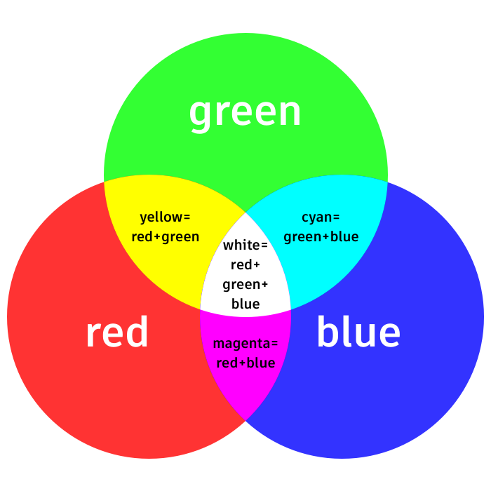
Additive, or light-based color has three primary colors: red, green, and blue. Mixing these three colors in different levels of intensity can create almost any color of light. Color changing LEDs work the same way, but the LEDs are all together in a small package we call an RGB LED. They have four legs, one for each color and one for either ground or power, depending on the configuration. The types are called "common cathode" and "common anode," respectively.
Step 1: Build the Circuit

Find this circuit on Tinkercad
In the Tinkercad Circuits components panel, drag a new Arduino and breadboard along side the sample, and prep your breadboard by connecting Arduino 5V to the power rail and Arduino GND to the ground rail.
Add an RGB LED and place it across four different rows of the breadboard. The RGB LED in the simulator has a common cathode (negative, ground) at its second leg, so wire this row/pin to ground.
Add three resistors (drag all three or create one and then copy/paste) and move them to the breadboard rows for the remaining three LED pins, bridging across the breadboard's center gap to three separate rows on the other side.
Connect wires from the free resistor ends and to three of your PWM-capable Arduino pins, which are marked with a tilde (little squiggle).
Tidy up your wires by adjusting their colors (dropdown or number keys) and creating bends (double click).
Although you may be tempted to consolidate and use a single resistor on the common pin, don't! Each LED needs its own resistor since they don't draw exactly the same amount of current as each other.
Extra credit: you can learn more about LEDs in the free Instructables LEDs and Lighting class.
Step 2: Color Mixing Code With Blocks
In Tinkercad Circuits, you can easily code up your projects using blocks. We'll use the code editor to test the wiring and adjust the LED's color. Click the "Code" button to open the code editor.

You can toggle between the sample code and your own program by selecting the respective Arduino board in the workplane (or dropdown menu above the code editor).
Drag an RGB LED output block into a blank program and adjust the dropdowns to match the pins you connected earlier (11, 10, and 9).
Choose a color and click "Start Simulation" to watch your RGB LED light up. If the color doesn’t seem right, you probably need to swap two of your color pins, either in the wiring or the code.
Create a colorful light show by duplicating your RGB output block (right click->duplicate) and changing the color, then adding some wait blocks in between. You could simulate a racetrack countdown, or color changes to go with your favorite song. Also check out the repeat block-- anything you put inside will happen on repeat for the specified number of times.
Step 3: Arduino Code Explained

When the code editor is open, you can click the dropdown menu on the left and select "Blocks + Text" to reveal the Arduino code generated by the code blocks.
void setup()
{
  pinMode(11, OUTPUT);
  pinMode(10, OUTPUT);
  pinMode(9, OUTPUT);
}

void loop()
{
  analogWrite(11, 255);
  analogWrite(10, 0);
  analogWrite(9, 0);
  delay(1000); // Wait for 1000 millisecond(s)
  analogWrite(11, 255);
  analogWrite(10, 255);
  analogWrite(9, 102);
  delay(1000); // Wait for 1000 millisecond(s)
}
After setting up the pins as outputs in the setup, you can see the code uses analogWrite() like in the last lesson on fading an LED. It writes each of the three pins with a different brightness value, resulting in a blended color.
Step 4: Build the Physical Circuit (Optional)

To program your physical Arduino Uno, you'll need to install the free software (or plugin for the web editor), then open it up.
Wire up the Arduino Uno circuit by plugging in components and wires to match the connections shown in Tinkercad Circuits. If your physical RGB LED happens to be common anode, the second pin should be wired to power instead of ground, and the brightness values 0-255 are reversed. For a more in-depth walk-through on working with your physical Arduino Uno board, check out the free Instructables Arduino class (a similar circuit is described in the second lesson).
Copy the code from the Tinkercad Circuits code window and paste it into an empty sketch in your Arduino software, or click the download button (downward facing arrow) and open the resulting file using Arduino.
Plug in your USB cable and select your board and port in the software’s Tools menu.
Upload the code and watch your LED change color!
Step 5: Next, Try...
Now that you know how to control RGB LEDs, it's time to celebrate your digital and analog output achievements! Using the skills you've picked up previous lessons on controlling multiple LEDs and using analogWrite() to fade, you've created a single pixel just like the (much smaller) ones inside the screens of your mobile device, TV, and computer.
Try covering up your LED with different diffusing materials to change the light quality. You could try making LED diffusers from anything that lets light through, such as ping pong balls, polyester fiber fill, or 3D printing.
Next up in your Arduino journey, try learning to detect input with pushbuttons and digitalRead().
You can also learn more electronics skills with the free Instructables classes on Arduino, Basic Electronics, LEDs & Lighting, 3D Printing, and more.


