

Introduction: ROV Submersible (PVC)


Ever since fishing up in the North of Norway in my grandfathers new boat I have been wanting to make an ROV(Remotely Operated Vehicle) submarine to observe the seabed from the surface.
So,I researched for parts and prices, and using the info I found I sketched out my first design!
***NOW UPDATED***
Check step 12+ to see how you can build a waterproof ROV lamp.
***parts list***
-PVC pipes and links
-Xm broadband internet cable(depends on how far and deep you want the sub to go.Note;the longer and thinner the cable, the more power is lost along it, also you should think about pressure resistance when choosing the lenght of the cable)
-Epoxy glue and epoxy putty
-motors x3(waterproof) I used water pumps
-plexiglass (20x20cm)
-12v battery or power supply(i used conventional AA batteries(10 of them) i know, its stupid but untill i can figure out another way of powering the sub it's going to have to do
-sillicone
-Camera housing parts (see pics)
-spray paint
-lots of zipties
-Webcam
-bolts for camera case (see pics)
-propellers (diam. about 2.5-3cm)
-small screws
-thin plastic tube for motor shaft extension
-and anything else that i havent mentioned but is in the pictures
**Tools needed**
-Metal saw
-Scissors
-wire cutters
-pliers
-small hacksaw
-and a few other easily obtainable tools
*some basic soldering, wiring and creative skills is required to make this:P
Step 1: Motor Test

Step 1:
(testing the motors and motor midifications)
---The main parts of the ROV are the motors, which enable it to move through the water in all directions.
In the picture you see me testing one of the water pumps which i bought to use as a motor.
---later I will be showing you how to make propeller shafts and attatching the proppellers.
Step 2: Cutting Away Unneccesary Parts of the Motor Housing


Step 2:
(cutting off the pump chamber)
---Since I was going to attach a bigger propeller
on a longer shaft I needed to cut away the pump propeller chamber.
Step 3: PVC Parts Needed


Step 3:
(identifying the parts needed)
---Here is a picture of all the parts i used to make the mainframe and the camera housing.
The parts are made of PVC plastic and the pipe is 2.5 cm diameter.
---Here is a rough layout of how one side of the mainframe was going to look like.I found it very useful to mark all the parts, so i would know where each part belonged.
Step 4: Melting the PVC Pipes Together


Step 4:
(melting the pvc pipes and links together)
---The pipes had to be stuck together in some way or another, and after some research i discovered that the best way was to melt them together. So i used my kitchen gas stove to do this.
---In the second picture you can see the first side of the frame is ready, I have laid out the parts I prepared for the second side.
Step 5: Completed Frame


Step 5:
(Joining of the two frame sides, finishing the frame)
--- As you can see I have completed the 2 frame sides, and have stuck them together with crosspipes.
The frame is now very sturdy.
I haven't included the dimentions of the frame, as I expect you will want to design your own.
Step 6: Painting the Frame


Step 6:
(painting the frame)
---I decided to spraypaint my frame yellow(the standard ROV colour) and the camera housing black.
Step 7: Making the Camera Housing


Step 7:
(making the camera housing)
---To ensure that the camera wouldn't get wet i had to make a waterproof case and i decided to make it 'very' waterproof, so it could withstand the high pressure of deeper dives. (not that this first model would do that, but atleast i could reuse the case later on).
The design i made myself, but researched some general info on the internet.
---The main section of pipe seen in earlier pictures needed a lid for the back and a plexiglass 'window'in the front.
So i used a pvc pipe lid with a bit of plexiglass with drilled bolt holes stuck to the lid with epoxy.I also smeared sillicone glue around the borders between the PVC lid and the plexiglass to make sure they couldn't separate.(as seen in second pic)
---I then cut some strong bolts i needed to keep the lid, pipe, and the plexiglass window together to the right length.
---The whole case is made waterproof by the bolts pushing the plexiglass surfaces against the washers at both ends of the pipe.
Step 8: Mounting the Camera


Step 8:
(mounting the camera into the housing)
--- I removed the original stand from the webcamera and replaced it by my own, smaller version.
---I also epoxy glued a nut to the camera housing so i could bolt the camera.
---Then i drilled 5 holes in the back lid:
1-for the camera wire to the surface
1-for the power wire to the surface
3- for te motors.
Step 9: Wiring


Step 9:
(wiring motors, power lines and camera)
---Wiring is one of the most tedious parts of the work i did, but cosidering i had very little previous experience im glad that i managed it.
---There are many ways to wire the ROV (check out this page http://www.homebuiltrovs.com/ , it explains some of the best methods very well.
-I used a very basic way of wiring as shown in the picture below.
Step 10: Closing It All Up


Step 10:
(closing up the camera case and attaching it to the mainframe)
---This step is where you have to try to fit everything (wiring connections) into the camera case...not an easy job :)
---just look through the pictures as there is no way of explaining :P
---finally i ziptied the camera housing to the frame
Step 11: Finishing Off (testing)


Step 11:
(testing it in the bathtub)
---To test that nothing was leaking I tryed the ROV in my bathrub
the results were good but I still have some buoyancy issues to fix.
---I also checked out some places by the seaside that i could test my ROV. See the pictures.
---Good luck making one, hope you enjoyed my first instructable.
I have lots of projects going on and older ones that i have to document and i will try to have them up as quick as possible.
Step 12: Building the Lamp

Step 12:
(the sub needs a source of light down in the depths)
---Many readers have asked me if I have any plans for adding anything more to my ROV. Yes, i have. Unfortunately i havent had all that much time to work on it, but here is what i have been able to make in the last couple of weeks. The waterproof ROV lamp.
***Parts you'll need for the lamp***
-PVC parts(i used some common fittings from a kitchen sink piping system as thats what i had available at the time and they suited the purpose of having a screwable cap with a hole for a 'window')
-Plexiglass(for the 'windows')
-sillicone sealant(to fill in those holes :P)
-rubber washers
-some wire
-tape
-a Dot-it 3LED lantern(i used one of these as it already had the circuitry readymade and it would be quicker)
-AAA batteries for the lantern
-one small switch
(sorry all the materials are not in the picture, but in later pictures you can see them)
***Tools***
-pliers
-cutting knife
-solder set
-scissors
-screwdriver(phillips)
Step 13: Disassembling the Lantern


Step 13:
(getting the guts out of the LED lantern and wiring the batteries and switch)
---Since i couldn't find any other way to open the lantern i had to break the plastic open. Some models have small screws and are quite easy to open.
---Once you have opened it. You want to remove and keep the pcb with the LED's attached to it, the chrome reflector plate and the transparent plastic shield lid. The AAA battery holder won't be neccesary. I didn't use mine as i couldnt fit it into the PVC tube.
Step 14: Closing Up the Holes, and Making the Window


Step 14:
(making the window)
---Since my pipe had two screw on caps with holes in to connect other pipes to it, i had to block both the holes. The front one was to be the light 'window'. The other one i used the plastic transparent glasspiece that i took out of the lantern, as it fitted perfectly.
---Put a thick lining of sillicone around the inside edge of the screw on cap, and push the plastic piece into place, avoiding too much stray sillicone(keep it clean and neat :P). I figured i could use this extra pipe attatchment hole to add a mechanical arm or some other device to it. Smear some more sillicone around the screwing rings of the cap. Then screw the cap on tightly and let dry.
---Now for the lamp window.
Sand the chrome light reflection plate so that it is slightly smaller than the rim of the cap.
Now trace the shape of it plus 3mm extra onto the plexiglass and cut it out. Make sure it fits tightly into the cap.
Then put a blob of hot glue in the center of the chrome reflector plate and stick it in the center of the plexiglass circle.
Now let it dry.
Step 15: Wiring the Electronics


Step 15:
(wiring the LED's to a battery)
---Solder two wires to the PCB board to which the LED's are attatched as in the picture.
---Now Connect the AAA batteries in series by taping them together and connecting with wires. If you have a small battery holder then that would be better, but i didn't have one.
---Connect them to the LED's and voila, we have light!
---Now cut one of the wires and solder a switch to it. This i did as i would stick the LED board to the window/plexiglass and reflector piece, so the plunging switch on it wouldnt be accessible.
Put a blob of glue onto the connection point to make sure the soldering doasnt come undone.
The electronics are now ready...
Step 16: Finishing Off


Step 16:
(putting it togethet and closing up)
---Put some hot glue around the LED's and press them into the holes in the reflector plate. Make sure that you dont get any glue on the tops of the LED's. And let it dry.
--- Now clip off the unecessary corners of the triangular PCB, so that it fits into the tube(pipe).
---Arrange the battery inside the pipe. Put a rubber washer between the rim of the pipe and the plexiglass disc. Now fit everything inside, and screw the cap on.
You'll have to open the front window to turn the light on and off.
---Later im considering adding a light resistor to the circuit so that it turns on and off depending on the light conditions.
Step 17: Photos of the Lamp


Step 17:
(the step that you watch and enjoy :D)
Here are some underwater pics of the lamp, including some underwater pics of my ROV in my bathtub...yeah, sorry i havent yet been able to get to a pool. But the ballast problems have been solved, simply by turning the ROV upside down in the water, all i need to do now is add a little bit more weight to the top so it gets neutral weight.
Step 18: ROV Update


Here are a few things i have done to the ROV in the last week.
-Added a frame to the top/bottom (top in the water, bottom on land)
-Bought a sealed lead-acid 12V battery (it came withought a charger, anyone know how i could charge it?)
-Made some havy PVC weights (pvc pipes with metal in them) to strap to the bottom of the ROV for buoyancy ballance
-Bought some relays (turned out to be the wrong kind) and 3 way switches to make a control box.
-Made the control box (pic's are coming soon)
-And this saturday i'm going to do the maiden vayage in my friends' pool..video's will be coming :D
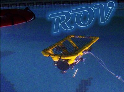
Step 19: ROV Test in Pool


Finally i have managed to test the ROV.(thanks Ben, Zac and Kat ;P)
And it was awesome!!
Never expected that 6 months of work would give me such a good result.
Well here are the pics, and the video both from onboard the ROV, from the surface and from my underwater camera.
;) enjoy
First Prize in the
SANYO eneloop Battery Powered Contest
Participated in the
SANYO eneloop Battery Powered Contest
Participated in the
Craftsman Workshop of the Future Contest


