

Introduction: Raspberry Pi 2 DIY LED LAN Device Counter


Do you know how many devices are on your local network? That is what we where wondering at our hackerspace HackBergen.
Yes, there are available programs and Apps to scan your network, but we can also scan with the Raspberry Pi (RPi) and show the result on a set of 7-segment displays.
These look cool, retro, are cheap and can be seen from a distance for you to have a general idea of how many devices are currently operating on your local network in these IoT times.
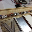
This build uses 3 modules of 7-segment common Anode LED displays that are controlled by an Atmega328. We use 3 because normal home LANs are C nets with a maximum of 256 devices and I had 3 of these nice 7-segment displays lying around. :)
The (AVR Atmega) 328 is loaded with the Arduino bootloader on an Arduino Uno 28pin AVR and then programmed with the Arduino 1.0.1 IDE through the Raspberry Pi on board serial port. The software is the firmware that Sparkfun uses on their serial backpack, but we have to modify a couple of lines since they use a 32 pin SMD 328 instead of the normal 28pin DIP version from the UNO.
By using an 328 for this, we do not need more than the serial port's 2 pins to control the display, and all multiplexing and buffering is done by the 328. No need for a program to do the multiplexing of the 7-seg displays and be problematic with irregular timing. We can also use the built in i2c bus to control it if we want to.
Using the serial port makes it very easy to display 7-seg chars on the display, remaining there until we update it again. This is great for piping information from scripts, and we do not need a program running constantly as a daemon.
You could of course buy a single 4 digit display from SparkFun ready-made and connect it to your Linux box or your RPi, losing all the DIY fun. That is totally up to you. :)
Step 1: What Hardware Do We Need?


- Soldering Iron with de-soldering gadgets
- Multimeter with continuity tester
- Wire
- Perfboard
- Lupe or magnifying glass to check the soldering
- Sharp or X-acto knife
- Arduino Uno
- 3 pcs common Anode 7-segment display
- Atmega AVR 328 DIP 28pin IC
- Sockets
- These are optional, but makes it easier to sneak wires behind the ICs
- Resistors.
- I used a 8 DIP 180ohm network for the segments as I find these convenient for things like this.
- 220 ohm for driving the base of the transistors
- NPN transistors. We used the 2n2222.
- Raspberry Pi B, B+ or 2.
- Ribbon cable - 40 pins or 26. We could use 10pin but that might ruin the RPis header.
- Header connector
- Breadboards. Optional as you can just reflash the bootloader on the UNO, but we did use the UNO to program the 328 on a breadboard. It is only done once.
Step 2: Schematics/connections

What is connected to the 328 on our build:
- 10K resistor +3.3V / Switch GND
- RPi TXD pin 8
- RPi RXD pin 10
- LED dp -> pin 8 DIP resistor
- LED seg 3 transistor base resistor
- NC
- +3.3V
- GND
- NC
- NC
- LED g -> pin 7 DIP resistor
- LED c -> pin 3 DIP resistor
- LED f -> pin 6 DIP resistor
- LED a -> pin 1 DIP resistor
- LED e -> pin 5 DIP resistor
- NC
- NC
- NC
- NC
- +3.3V
- +3.3V
- GND
- LED b -> pin 2 DIP resistor
- LED d -> pin 4 DIP resistor
- LED seg 1 transistor base resistor
- LED seg 2 transistor base resistor
- RPi SCL pin 5 (optional)
- RPi SDA pin 3 (optional)
Original Schematics this is based on: Original 32 pin AVR schematics
Attachments

Step 3: Cut Out a Piece of Perfboard and Start Soldering


Decide on a size you want by placing your components on the perfboard and cut it out with a knife or saw.
I have a Olfa plastic cutter I really love for things like this, but a normal sharp knife works fine.
Step 4: Install 328 Bootloader
There are a lot of great guides on how to program your Atmega 328 for simple use without external crystal 8Mhz use:
http://www.arduino.cc/en/Tutorial/ArduinoToBreadboard
Install Arduino IDE on the RPi so we can burn bootloader with the UNO:
- sudo apt-get install arduino (This installs arduino 1.0.1)
Install 8Mhz breadboard arduino ref: http://www.arduino.cc/en/Tutorial/ArduinoToBreadb...
- mkdir -p sketchbook/hardware
- cd sketchbook/hardware
- unzip /home/pi/Breadboard1-0-x.zip
- arduino
- check for and select tools->board-> ATmega328 on a breadboard (8 MHz internal clock)
- Make Link to serialport for arduino to discover after reboot
- sudo nano /etc/init.d/link_serial
- #!/bin/bash
- ln -s /dev/ttyAMA0 /dev/ttyS1
- sudo nano /etc/init.d/link_serial
- sudo chmod 755 /etc/init.d/link_serial
- sudo update-rc.d link_serial defaults
- sudo service link_serial start
- check serial port link, to see if it exists
- ls -l /dev/ttyS1
- run arduino IDE
- select tools->board->ATmega328 on a breadboard (8 MHz internal clock)
- Select tools->serial port->/dev/ttyS1
- Select tools->Burn Bootloader
- remember to push the reset button on your new board when compiling, right before upload
- You get "Done uploading" when OK or "problem uploading to board" if you wait too long. Just try again until you get it.
Step 5: Download and Install Firmware for Arduino IDE to Be Able to Compile
We downloaded the firmware onto Rpi using git, but use your personal favorite:
This software relies on the 7-segment software, that we also must download:
https://github.com/sparkfun/sevseg
I did not get the sketchbook/hardware directory to work with sevseg, so I unpacked it into
/usr/share/arduino/libraries as root.
Step 6: Make Modifications on the Serial7SegmentDisplay Code and Flash It
As our build is using the 28 pin version of the Atmega AVR 328, we need to change a few lines in the source:
Open Arduino IDE and load the
Serial7SegmentDisplay/firmware/Serial\ 7-Segment\ Display/Serial_7_Segment_Display_Firmware/System_Functions.ino
Then edit 2 files..
Serial_7_Segment_Display_Firmware.cpp
- #define DISPLAY_TYPE S7S
System_Functions.cpp under DISPLAY_TYPE == S7S
- int segE = 9;
- int segDP= 2;
- int digitColon = 22;
- int digitApostrophe = 23;
That's it. We basically did this just to swap the pins instead of changing pins_arduino.h
Now upload the program to the 328. You need to push the button approximately as the compilation ends and uploading starts.
Just try again a few times until you get it right.. :)
You can find the files we modified for use on the RPi for this project here: HackBergen RPi7-seg files.
Step 7: Connect Display to RPi and Test It.
- Power down RPi
- Connect ribbon cable between RPi and Displayboard
- Power up the RPi without SD card, just to see that the Displayboard works
- The next steps can be done when you have the AVR 328 loaded with the Serial7SegmentDisplay firmware:
The firmware shows 1 2 3 on the modules before anything is sent on the serialport.
If this shows up, you know everything is OK and that you have connected everything right.
- When the Displayboard works, boot up with SD card and log in as normally.
- There could be strange chars displayed on it as the RPi boots, this is normal.
- Manual test to display 123 on display
- echo "v123" >/dev/ttyS1
- v = clear display and reset cursor
- Which commands will work: Serial7SegmentDisplay Special commands
- printf is nice for formatting
- printf "v%3d" 123 >/dev/ttyS1
Step 8: Install Nmap, Edit Script and Run It With Cron
- sudo apt-get install nmap
- download nmapdisplay.sh from hackbergen github into /home/pi (or where you want it to be)
Install as root:
- sudo crontab -e
- PATH=/usr/local/sbin:/usr/local/bin:/usr/sbin:/usr/bin:/sbin:/bin
- # m h dom mon dow command
- */10 * * * * /home/pi/nmapdisplay.sh > /dev/null 2>&1
Step 9: Start Counting LAN Devices
If everything is OK, you should now have the number of detected devices on your fancy display!
And the RPi hardly uses any resources other than scanning your network every 10 minutes, so it could easily run a Media Center in addition.
This display could be used for a lot of things with more digits depending on what you need.
If you need more than 4 digits, you could use the unused pins and change the firmware and 7-seg library to handle that..
Step 10: Optional: Solder in the SCL/SDA Wires
My original plan was to control the display with the i2c bus, so I connected the SCL/SDA wires also.
There is no need for this with just one display, but the option is there if you enable i2c in the kernel with raspi-config. The /dev/i2c device was not correctly installed using raspi-config, so I had to alter some things manually:
- sudo nano /etc/modules and add
i2c-bcm2708
i2c-dev
- sudo nano /boot/config.txt and add
dtparam=i2c1=on
- sudo apt-get install i2c-tools
After that and rebooting (when the display module is connected) you could run
i2cdetect -y 1
And the display pops up as 71 like this:
pi@raspberrypi ~ $ i2cdetect -y 1
0 1 2 3 4 5 6 7 8 9 a b c d e f
00: -- -- -- -- -- -- -- -- -- -- -- -- --
10: -- -- -- -- -- -- -- -- -- -- -- -- -- -- -- --
20: -- -- -- -- -- -- -- -- -- -- -- -- -- -- -- --
30: -- -- -- -- -- -- -- -- -- -- -- -- -- -- -- --
40: -- -- -- -- -- -- -- -- -- -- -- -- -- -- -- --
50: -- -- -- -- -- -- -- -- -- -- -- -- -- -- -- --
60: -- -- -- -- -- -- -- -- -- -- -- -- -- -- -- --
70: -- 71 -- -- -- -- -- --


