

Introduction: Raspberry Pi Controlled Irrigation System


Every spring my wife gets really ambitious and plants a big vegetable garden. As the summer drags on, ambition turns to laziness and unfortunately many of the plants die a slow, withering death from neglect due to lack of weeding and watering (except for the tomato plants, which grow like mutants in our climate even if you neglect them...so every August we wind up with 10,000 tomatoes and no other vegetables).
While I can't automate some maintenance tasks like weeding*, I can certainly automate the watering and I figure that will give our poor plants a better chance at survival. You can buy all sorts of fancy programmable hose, irrigation, and water timers (not sure about the difference between those three terms, but that's how Lowe's has them listed) if you want to automatically water your garden. But, in the true spirit of Instructables...where's the fun in buying one when you could build it yourself? Enter the Raspberry Pi-Controlled Irrigation System. A quick search on Instructables shows that I'm not the first one to do this, but I think my project will take a unique approach. I really didn't want to deal with calibrating or cleaning a soil moisture sensor. I also don't care about being super picky about maintaining an optimal soil moisture level. The bar is set pretty low here - I just want to keep the plants alive. If we're watering the plants by hand, we roughly follow a rule of "Did it rain yesterday? If not, water the plants." So, why not automate that with a Raspberry Pi? Use a weather API to answer "did it rain yesterday?" and then the GPIO pins to control a solenoid valve to water the garden. That's what this Instructable will show you how to do, including the electronics, programming, and plumbing. The advantage of this approach is that it's flexible and easy to expand - for example, if I want to decide how long to water based on how much it rained, water based on the future forecast, or water in multiple short intervals throughout the day, that just requires changing a few lines of code.
Please note that this is not a "how to use a Raspberry Pi" Instructable. If this is your very first time using a Raspberry Pi, there are a TON of getting started with Raspberry Pi projects out there - please check those out first if you need answers to things like "how do I install the OS?" or "what type of power supply do I need?"
Ready to get started? Move on to the next step for a full materials list!
*Consider that a challenge. Someone needs to do a computer vision/robotics project that uses a camera to identify weeds and a robotic arm to remove them.
Note on contest entries:
- Sensors Contest: "If it’s got an input and an output, it’s fair game." - I hope that means the Weather Underground API counts as a sensor, even though I'm not using my own local rainfall sensor.
- Urban Farming Contest: OK, so I'm not exactly doing this on the rooftop of an apartment building, but you should be able to do this project regardless of your location (and this project is sort of a DIY version of the grand prize of that contest anyway)
- Home Hacks Contest: I certainly hope this is making a regular household task faster and easier, so this one seems like a good fit!
Step 1: Materials


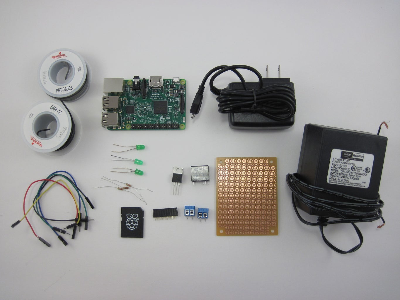
I got most of the parts for this project at SparkFun, Jameco, and Lowe's. I'll do my best to link the exact parts I used, but you can make reasonable substitutions and it should still work (e.g. you could use a different model Raspberry Pi, or you could do the whole thing with 1" PVC pipe instead of 3/4", provided you get all the right adapters). Note that the exact quantity of piping and types of adapters you need will depend on things like the size of your garden and whether you also want to have a regular hose connected, so you will need to take some measurements and plan your layout before you make a trip to the hardware store (see next step).
Update: thanks to many people on Reddit, Hackaday, and in the comments here for feedback on the electronics and plumbing. The biggest point seems to be that my original circuit was missing a flyback diode across the relay coil, so I've updated the instructions to include that. I've received other comments about including a current-limiting resistor on the RPi's GPIO pin, a pull-down resistor on the MOSFET gate, an RC snubber in parallel with the solenoid valve, and to use poly tubing instead of PVC, but I'll leave those changes up to the individual. If you have questions or advice on any of those points, please leave a comment.
Electronics
- Raspberry Pi 3. Used because it has built-in WiFi, but you could do this with an earlier model.
- 5.25V, 2.4A micro-USB power supply. Recommended for the RPi3, older models do not require as much current.
- Micro SD card with adapter. 8GB recommended, newer versions of Raspbian Jessie don't seem to fit on 4GB cards (unless you plan to install the lite version and only run headless).
- Relay. I debated using a solid-state AC relay, but this mechanical relay is rated for 100,000 operations at max electrical load - we are well below that limit if you're only watering a couple times a day.
- N-channel MOSFET. Required because the RPi's GPIO pins cannot drive the relay coil directly.
- 2-pin screw terminals (2)
- Protoboard or breadboard of your choice
- Green LED (3), used as status indicators
- Rectifier diode
- Male/female jumper wires, for connecting to Raspberry Pi GPIO pins
- 22 AWG solid hookup wire, for making connections on protoboard
- Female header pins
- 220 ohm resistor (3)
- 20 AWG stranded hookup wire, for connecting solenoid valve (note that you may need thicker wire if you need to run the wires really far, consult a chart like this to determine what you need)
- 24 VAC 1500mA AC to AC wall adapter. Important: make sure the rating of this adapter matches the requirements of the solenoid valve you purchase! (some valves are DC)
- Optional: monitor for Raspberry Pi. I found a monitor useful for setup and debugging, but once it's working you should be able to run the RPi headless (without a monitor). See instructions for connecting to the RPi remotely via VNC or SSH if you do not have a monitor.
- Project box (small cardboard box or plastic container)
Plumbing (note: NPT = National Pipe Thread, MHT/FHT = Male/Female Hose Thread)
- 3/4", 24VAC irrigation valve (1)
- Hose faucet Y-adapter (only needed if you also want to attach regular hose)
- Hose quick connectors (1 for faucet plus 1 per soaker hose)
- Coiled spring faucet connector (1)
- MHT to 3/4" slip adapter (1 for faucet plus 1 per soaker hose)
- 3/4" PVC pipe (qty depends on size of your garden)
- 3/4" PVC slip 90°elbows (minimum of 4, more depending on layout of your garden)
- 3/4" PVC slip T-connectors (required to split pipe if you have multiple soaker hoses)
- 3/4" PVC slip couplings (depends on size of your garden, if 10' pipe sections aren't long enough)
- 3/4" PVC slip ball valve (1)
- 3/4" PVC slip check valve (1)
- 3/4" PVC slip union (1)
- 3/4" NPT to PVC slip adapter (4)
- Soaker hoses (qty and size depend on size of your garden)
- PVC cement and primer
- Silicone caulk
- Waterproof wire nuts
- Waterproof project box big enough for solenoid valve (I used a small plastic tub)
Tools
- Hacksaw or miter saw to cut PVC pipe
- Shovel, hoe, or trenching spade etc. to dig trenches for pipe
- Wire strippers
- Soldering iron
Step 2: System Diagram and Planning


Confused about how all those parts fit together after reading the materials list? Here's an exploded diagram of the entire plumbing system (more details on the electronics in a later step). The exact dimensions and orientations will depend on the layout of your garden and relative location of the hose faucet. You should definitely plan your layout in advance and do a "dry run" (cut straight pieces to length, lay out all the pieces of piping in their approximate locations to make sure they'll fit). Mistakes in this project can be hard to undo - you don't want to start haphazardly digging holes in your yard and cementing pieces of pipe together only to find out halfway through that things don't fit together right.
A couple important notes:
- Pay attention to the difference between NPT (national pipe thread) and MHT (male hose thread) adapters. They look similar at first glance, but the threads aren't compatible. NPT adapters are used to connect to the solenoid valve and PVC union. MHT adapters are used to connect to the hose faucet and soaker hoses.
- The entire section in the dotted red box (between the faucet and the PVC union) can be disconnected and brought inside during the winter. This prevents any damage to the solenoid valve if leftover water inside it freezes. I believe the standard approach is just to bury the valve below the frost line, but I wanted easy access to the valve in case something went wrong (this being my first attempt at a DIY irrigation system) or I wanted to make changes to the future. If you just want the valve permanently installed, you can get away without the union and quick connector.
- Make sure you install a drain valve at the lowest point in the system! Again, this is so you can drain out all the water and prevent damage from water freezing in the pipes over the winter. I forgot to do this at first so had to dig up and cut a section of pipe to add a T-connector for the drain.
- "Call before you dig" - you might have seen this phrase on little flags or utility boxes around your neighborhood. If there are any underground utility lines (gas, electric, water etc.) in your yard, make sure you know where they are and avoid them. If in doubt, call the utility company to be safe and they will mark the lines for you.
- I recommend using an indoor outlet for the 24VAC adapter, as it is not rated for outdoor use. I ran the wires through a window. If you must use an outdoor outlet, make sure to use an appropriate weather-rated adapter.
Step 3: Dig Trenches


Dig trenches where you'll need sections of underground pipe. Note that there is probably some rule of thumb about how deep these trenches should be, and I didn't follow it. My trenches are only a few inches deep, just enough to bury the pipes and cover them with some soil. If that's a terrible idea, please let me know in the comments and I'll update this step.
Update: someone already pointed out that you risk cracking the pipes when you step on them if they're not buried deep enough. So, bury your pipes deeper than pictured here.
Step 4: Lay Pipe


Follow the instructions on the PVC primer/cement to lay out the sections of pipe and various slip connectors. These sections should be terminated with slip-MHT adapters and quick connectors for the soaker hoses (refer back to diagram in step 2). Don't forget the drain valve!
Step 5: Put Solenoid Valve in Plastic Box


- Screw NPT-slip adapters into both ends of the solenoid valve.
- Drill two 1" holes opposite each other in the sides of your plastic box (note that 3/4" PVC pipe refers to the inner diameter, the outer diameter is 1").
- Push straight segments of PVC pipe through the holes and connect them to the slip adapters inside the box. Remember to use PVC primer/cement to seal the joints.
- Use silicone adhesive to seal around the perimeter of the holes you drilled.
- Important: drill a few small drain holes in the bottom of the box. I found out this was necessary when I realized I had a few small leaks because I didn't tighten the adapters enough.
Step 6: Connect Solenoid Valve to Rest of System


This is the most complicated plumbing step in terms of adapters and valves. Each part is labeled in the photo above (I disconnected the valve from the rest of the system so I could get a clear photo), but you can also refer back to the diagram in step 2. It might be easier to assemble this segment inside or on a workbench, then take it outside to connect it.
Important: Make sure you get the flow direction of the check valve correct! The valve has an arrow on it that indicates flow direction. This arrow should point towards the solenoid valve (to the right in the photo above). A check-valve is a one-way valve that will prevent dirty water from flowing backwards into your house, if for some reason the pipes in your house lose pressure. I'm not 100% sure if this is necessary (I've never seen a check valve installed on a regular garden hose, which can have dirty water sitting in it), but after some Googling about sprinkler systems, I figured better safe than sorry.
Step 7: Attach Solenoid Valve Wires


- Cut two segments of stranded 20 AWG hookup wire (length depends on how far you need to run the wires into your house).
- Drill small holes in the sides of the plastic box and thread the wires through.
- Connect them to the solenoid valve wires with waterproof wire connectors.
- Use silicone to seal around the holes.
- Run the wires into your house to wherever you plan on having the Raspberry Pi set up. I poked a tiny hole in a screen and threaded them in through a window. You will connect these wires to your circuit in the next step.
Step 8: Check for Leaks!


Before you go any farther, you probably want to check your plumbing for leaks. Luckily you can do this before you even make the circuit or hook up the Raspberry Pi. Take the two solenoid valve wires you just ran inside, and twist them directly to the two wires from the 24VAC adapter (note: if your adapter ends in a barrel plug, cut it off then separate and strip the wires). This will open the valve and water should flow through your pipes. If you can't hear water flowing, check that you've opened any other necessary valves, like the hose faucet and internal shutoff for the pipe.
Hopefully you don't have any leaks at your cemented joints, or you might have to cut the pipe and re-do the joints. I had a few leaks at threaded joints, particularly the union, that required tightening. Note that you can tolerate slow leaks downstream of the solenoid valve, because those areas will only be pressurized when the valve is open. However, you really do not want leaks upstream of the solenoid valve (between the hose faucet and solenoid valve), because those will be pressurized all the time and will leak continuously.
Finally: I'm not sure if I'm violating some rule about mixing plastic and metal threads, and if that could contribute to leaks. I didn't have much of a choice because I had to get from a metal hose faucet to plastic PVC somehow. If you have any input on that point, please leave a comment.
Step 9: Circuit


The images above show a breadboard diagram and schematic of the circuit. This should be clear to assemble based on the diagrams, but leave a comment if you have questions. I recommend testing everything on a solderless breadboard (see next step) before you finalize the circuit on protoboard.
Here's how it works:
- A relay controls the 24VAC power to the solenoid valve.
- The relay coil requires 5V and the Raspberry Pi's GPIO pins are only 3.3V. So, the Raspberry Pi drives a MOSFET which turns the relay coil on and off, which then turns the solenoid valve on and off. By default, when the GPIO pin is low, the relay is open so the valve is closed (water does not flow). When the GPIO pin goes high, the relay closes, and the valve will open (water will flow).
- I added a couple status LEDs to use as indicators. One is connected directly to the RPi's 3.3V supply, so you know your circuit is getting power. Another will be turned on when the solenoid valve is open, and the third is in there just in case I think of something else to use it for.
Note that Fritzing did not have a relay that matches the pinout of this SparkFun part. I was too lazy to make a new Fritzing part so I just edited the breadboard diagram in Inkscape, which is why the relay and wires connected to it look a little different. If you feel like making a new Fritzing part (which SparkFun has a tutorial on), let me know and I can update the Fritzing file.
Also note that I forgot to include a flyback diode across the relay coil initially, so it isn't shown in the picture (but I did update the Fritzing diagrams).
Finally, not a bad idea to put everything in a project box once you've finished the circuit board. A SparkFun box with some holes poked in the sides for the wires works nicely.
Attachments

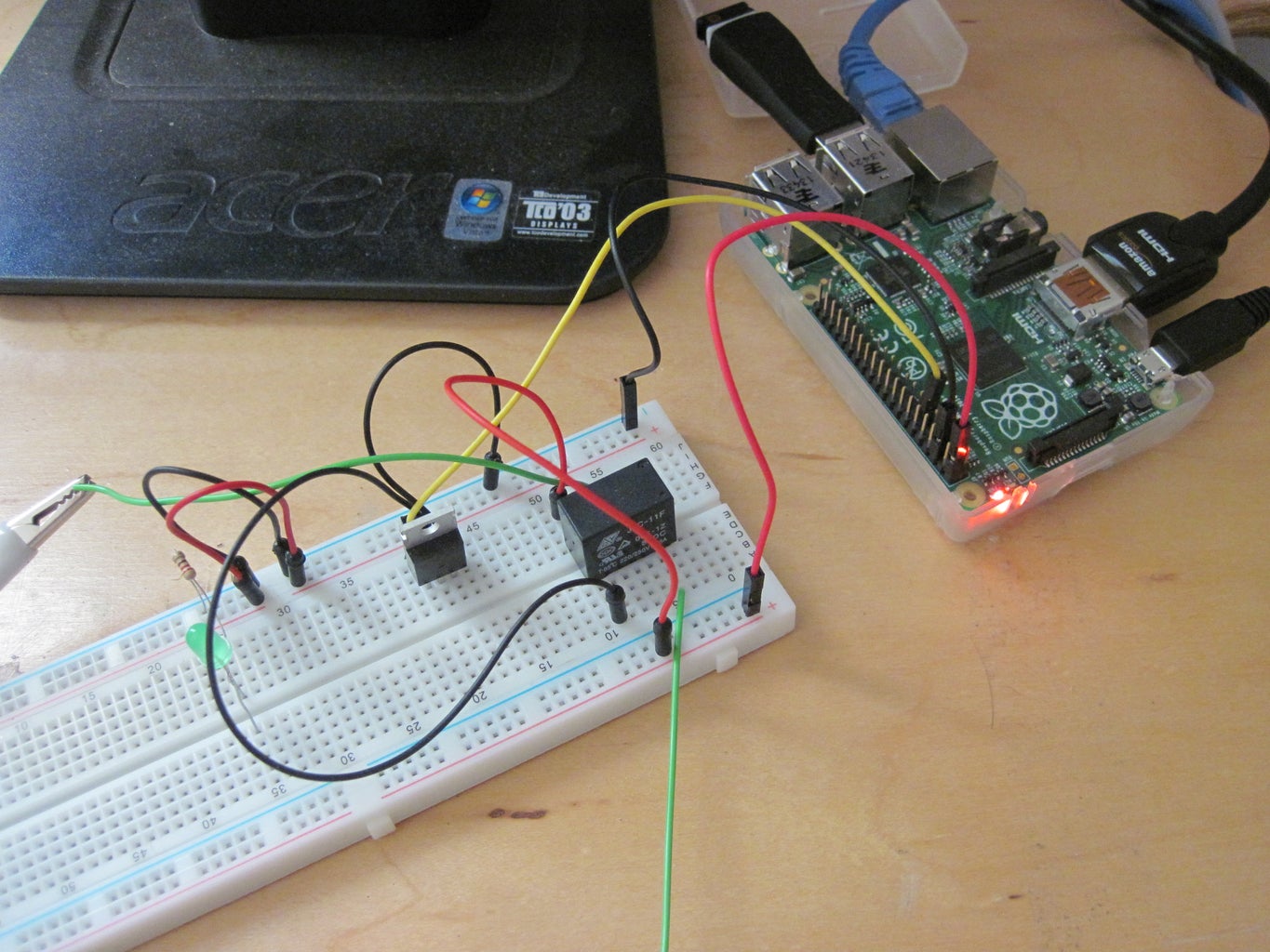
Step 10: Testing Circuit
Before you go for full-blown automation, it's a good idea to test the circuit manually. You can do this by using the command line in Python. Please remember that I am assuming you have basic knowledge of how to use a Raspberry Pi at this point. If you find yourself asking questions like "how do I install the operating system?" or "how do I launch Python?", you should check out the many Instructables on getting started with Raspberry Pi or the Raspberry Pi Foundation's official learning resources before you continue.
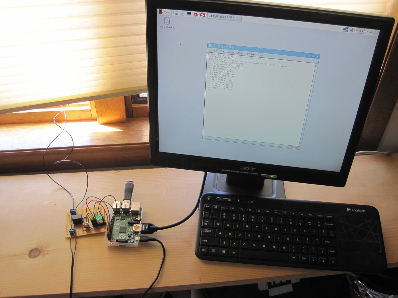
To test your circuit, power up your Raspberry Pi (the top LED on your circuit board should light up since it is connected directly to the 3.3V supply), then open Python and enter the following commands:
import RPi.GPIO as GPIO
GPIO.setmode(GPOI.BCM)
GPIO.setup(17,out)
GPIO.setup(27,out)
GPIO.setup(22,out)
This initializes the GPIO pin controls and sets pins 17, 27, and 22 as outputs. Now type
GPIO.output(27,GPIO.HIGH)
GPIO.output(22,GPIO.HIGH)
This should turn on the other two status LEDs. You know things are working so far. Now for the big test (drumroll). Type
GPIO.output(17,GPIO.HIGH)
You should hear a "click" as the relay switches position. Go outside and check your solenoid valve. It should be open and water should be flowing. Assuming you checked for and fixed any leaks previously, this means everything is working! Now, go back inside and type
GPIO.output(17,GPIO.LOW)
You should hear another "click" from the relay. This turns the valve off. Go back outside and check that the water has stopped.
Great so far...but you don't want to have to type a bunch of commands every time you want to water your plants. Now it's time to automate the whole thing!
Warning: do not use GPIO.cleanup(). Through a few hours of irritating troubleshooting, I found that this command (for reasons I still don't fully understand) causes the relay to turn on again, opening the valve. The best explanation I can find came from this Stackexchange thread where a comment states that "The cleanup method sets all the gpios you have used to be inputs and disables the internal pull-ups/downs for those gpios." You need the pin to stay as an output with a low voltage to keep the relay off, so that could cause the problem. I tried adding a 10K pull-down resistor to the MOSFET gate but that didn't work. So, even though it's generally recommended as good practice, I'd avoid using GPIO.cleanup() for this project. Please leave a comment if you have a solution here.
Step 11: Code
Now that you have a working circuit and plumbing system, you will install code on your Raspberry Pi that automatically checks the past 24 hours' rainfall and decides whether or not to open the solenoid valve. Then you'll have a hands-free watering experience!
Credit for the code for this project goes to my friend Mark Veillette. The files and installation instructions are available on his github page: https://github.com/markveillette/rpi_sprinkler. The code is pretty well-commented but here's a general explanation of how it works:
- run_sprinkler.py is the main file that checks a weather API for the past 24 hours' rainfall, decides whether or not to open the solenoid valve based on the rainfall amount, controls the GPIO pins, and writes the resulting actions to a log file.
- config is a configuration file where you enter your Weather Underground API key, your city/state, the GPIO pins used by the circuit, and the rain threshold (in inches) for running the irrigation system.
- run.crontab is a scheduling file where you set when run_sprinkler.py will run, using Cron, a Linux job scheduler. This has the advantage of only running the Python code briefly at certain times of day, rather than leaving a Python script running in an infinite loop 24 hours a day and constantly checking the time (like I did in my Christmast light timer project...whoops). By default it is set to run twice a day at 6am and 6pm, but this is highly customizable. For example, you could set it to only run every Tuesday and Thursday, or only on odd days of the month.
To get it running, follow the download and installation instructions on Mark's Github page. Be sure to go through the recommended testing commands to make sure everything is working smoothly. Then, let it run for 24 hours, come back to check the log file, and make sure the results are consistent with weather you actually observed (in other words, if it didn't rain, it should have turned on the sprinkler and the log file will say that). If you have any trouble getting the code to run, please post a comment along with any error messages you received and I'll do my best to help out.
(Note that Mark decided to call it a "sprinkler" - that's more compact than "irrigation system," so whatever. They refer to the same thing.)
Step 12: Grow!
Make sure you monitor the entire system for a few days to confirm that it's running smoothly. Check the plumbing for leaks and check the log file to make sure the program's actions are consistent with the weather you observe. Most importantly, check the health of your plants! You don't want to over or under-water, so adjust the timing and duration of the watering in the run.crontab and config files as needed (see the Github page for instructions on making changes to the files). This is where some actual gardening know-how would come in handy, because I'm doing the timing by trial and error - any suggestions for typical watering times using soaker hoses for a vegetable garden in the Northeast would be appreciated.
Any other questions or suggestions? Don't hesitate to leave a comment - thanks for reading!

Runner Up in the
Sensors Contest 2016

Runner Up in the
Home Hacks Challenge

Participated in the
Urban Farming Contest


