

Introduction: Raspberry Pi Portable Games Console


Building this Portable Games Console is possibly the most fun I've had using a Raspberry Pi. And it's not just the build that's fun; I've now got a fully functioning games console, so I can play all my favourite old arcade games, on-the-go!
There's a quiet a few other projects out there where people have done similar things and I've used them for help along the way. Projects like the Adafruit Cupcade and Ben Heck's PiMAME, but these often have complicated powering solutions and can be pretty tricky to build.
The power option I've gone for is the PiJuice. It's an integrated battery module specially built for the Raspberry Pi (complete with our revolutionary PiAnywhere technology – the best way to take your Pi off the grid!). It makes the whole project simple and neat and means that I don't need to mess around with charging circuits and power converters.
I started off using the PiJuice when I built the Raspberry Pi Compact Camera, and that's when I realized it's potential to be used in this Portable Games Console.
I'm glad to here of any ideas you have for other great solar or portable projects. Let me know in the comments and I'll do my best to create a tutorial!
For more information on the PiJuice head over to our Kickstarter and you could be the proud owner of a Games Console Maker Kit + PiJuice:
https://www.kickstarter.com/projects/1895460425/pijuice-a-portable-project-platform-for-every-rasp.
Step 1: Parts

1 x Micro SD and Micro SD card reader
1 x Arduino Pro Mini (5V/16MHz)
4 x Tactile Switches
10 x Female-Female jumper leads
8 x Jumper wire pin connecters
Right angle headers (set of at least 25 pins)
1 x Laser Cut Kit
PC or laptop with a linux operating system
Step 2: Download AdvMame for Raspberry Pi

The first stage is to download the games console image. The version used here is something called “cupcade”, developed by Adafruit, it utilises Shea Silverman’s AdvMAME emulator and is adapted to run smoothly with the Adafruit 2.2” TFT screen. The image is available for download from here and can be written to an SD card using your preferred method
It’s a good idea to check at this stage that everything is working properly, but first you'll need a game to play. Here is a set of legal ROMs to download straight from the MAME website. Download the desired ROM to your PC. With the SD card still in the PC copy and paste or drag and drop the the ROM from download into the ROM folder on the SD card, located in the advmame directory. The ROM should be left as a zip file.
Now everything should be set to play your game; plug the SD card into your Raspberry Pi and connect a USB keyboard. This is a good time to test out the PiJuice: It plugs into the GPIO on the Raspberry Pi as seen in the diagram. Fortunately, the PiJuice has a breakout so that all of the Raspberry Pi GPIO are still available and the screen just sits on top, like a PiJuice Sandwich.
Step 3: Custom Games Controller - Joystick


The output from the joystick is two analog signals for x position and y position ranging from 0 to 5V. The Arduino is used as an analogue to digital converter since the Raspberry Pi doesn't have any analogue pins.
If you wanted to try this project yourself, you'll need to do some soldering, so ensure you are comfortable with using a soldering iron safely. If you are at all unsure, ask for the help of somebody who is competent with soldering.
First, right angle headers are soldered to the Arduino on the following pins:
- Pin A0 - for input from joystick in x direction,
- Pin A1 - for input from joystick in y direction,
- Pins 2,3,4 and 5 for output of a digital state to the Raspberry Pi GPIO, (up, down, left and right).
- VCC and GRD for powering the Arduino
- VCC and GRD for powering the joystick
Then wires are soldred to the TFT screen in the following way:
- A red wire with female end (~7cm) to 5V pin on TFT screen to power the Arduino
- A Black wire with female end (~7cm) to GRD on TFT screen. This is the pad marked with "WP" located on the underside of the screen.
To program the Arduino, it is connected to a computer using a USB to TTL adapter. It's programmed using the Arduino IDE. (If you do not already have the Arduino software installed it can be downloaded from the Arduino website.) Make sure that the correct board is selected under Tools>Board. This is where the the code for the analogue to digital conversion can be uploaded to the Arduino. It's available on to the PiJuice Github page.
Step 4: Custom Games Controller - Buttons


The wire connecters are solder to each tactile switch in the diagonal positioning as seen in the picture. One side of each switch is connected to ground and the other is connected to a GPIO input on the Raspberry Pi.
To connect each switch to ground I made a 4-1 junction as seen in the picture, this requires soldering and using heat shrink to wrap the junction. Another female jumper is soldered to the ground pad on the screen for connecting to the junction.
To connect the other sides of each switch to the GPIO, right angle headers are soldered onto the GPIO breakout on the TFT screen. First, two right angle pins onto pins 17 and 27, these will be the [insert coin] and [start 1p] buttons. Then, a row of headers into pins 5, 6, 12, 13, 16, 19, 20 and 21. These will make up four action buttons and four direction buttons.
Then using an assortment of jumper leads everything is connected up:
- VCC Arduino - VC Joystick
- GND Arduino - GND Joystick
- A0 Arduino - Joystick X
- A1 Arduino - Joystick Y
- 2 Arduino - GPIO 12 RPi
- 3 Arduino - GPIO 13 RPi
- 4 Arduino - GPIO 20 RPi
- 5 Arduino - GPIO 21 RPi
- VCC Arduino - 5V RPi
- GND Arduino - GND RPi
(The ordering of the buttons is not important at this stage)
- Button 1 - GND RPi and GPIO 5 RPi
- Button 2 - GND RPi and GPIO 6 RPi
- Button 3 - GND RPi and GPIO 17 RPi
- Button 4 - GND RPi and GPIO 27 RPi
The next step is to get the software to map GPIO input to keyboard function.
Step 5: Retrogame


To use the GPIO as input for the controls rather than a keyboard I used some software in the background. The is called Retrogame written by Adafruit.
Download the Retrogame zip file from here onto a linux pc.
Open up a file viewer with root privileges and copy and paste the Retrogame file into the home>pi directory.
Now you can edit the file on the Raspberry Pi using an SSH client with your Raspberry on the local network. Unzip the Adafruit-Retrogame-master.zip and open up retrogame.c (sudo nano....).
In retrogame.c there's a table which outlines which GPIO replaces which keyboard function. These can be changed to suite your own needs mine is set to match the picture above.
retrogame.c is compiled and ran using "sudo make retrogame.c" and "sudo ./retrogame"
Again, this is a good time to check that everything is working properly, before the whole thing is assembled. With retrogame running, start up a ROM, fingers crossed...
We're Gaming!
To make retrogame.c run on boot edit rc.loacl and add "home/pi/Adafruit-Retrogame/retrogame &" before the final "exit 0" line.
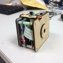
Step 6: Assembling the Console


Now that everything is all working, and powered completely off the grid, with the aid of the PiJuice, the final stage is to put everything together.
If you wanted to follow this guide, you could always build your own simple chasis to house all of the components. It wouldn't be too hard to make something suitable.
I'm really happy with the finish off this project and all fits nicely into one single unit. However, this is just a prototype! We're making a number of improvements so that it's going to be even easier for other people to build.
If you want the official completed Games Console project kit including chassis and PiJuice module then you could always head over to the Kickstarter page and pre-order the "Maker Kit" to get the essential parts required to build the compact camera, games console and Portable PocketPi.
Like I said earlier, if you've got any ideas for some cool projects, let me know!

Second Prize in the
Pi/e Day Contest


