

Introduction: Raspberry Pi - Revision 2 DIY Add-On Board


On the Raspberry Pi, there are several connections which can be used for expansion:
1, The Rpi GPIO (General Purpose Input/Output) pins are exposed, that means that expansion
boards are able to talk directly to the CPU.
2, The DSI connector will allow low-level interfacing with LCDs and other displays.
3, The CSI connector will allow camera modules to be added in future.
Step 1: Raspberry Pi Single Side DIY Add-on PCB With 5V/3A Buck Regulator Power Supply.

Features:
- 5V/3A power-supply
- buffered interface to GPIO pins
- 4 button switch
- 3 LED [include 1 hardware PWM] - external connectors also available
- 1 Relay
- 5V logic Level UART interface
- 16x2 LCD [74hc595 based] with back light control option
- SPI ADC MCP3008
- DS1307 with battery backup holder
- 24C032 EEPROM
- PCF8591 DAC_ADC
- i2c external connector [3.3v to 5V logic converter included]
Step 2: Block Diagram of Add-on Board

block diagram representation
LM2587 Buck regulator : 5V/3A power supply
3.3v to 5v level shifter : ic74HCT125 -single direction
3.3v to 5v level shifter for i2c : MOSFET 2N7000 based -bi directional
24c032 :eeprom
battery: 3V RTC backup battery
DS1307 : i2c based RTC chip
PCF8591: i2c based ADC-DAC chip
4 switch: user input button switches
MCP3008: SPI based 10-bit Analog-to-Digital Converter
74HC595: 3 wire serial LCD interface
16X2 LCD: 16 character x 2 line monochrome LCD [serial interface -74hc595]
LED 1-3 : LED output 3 color LED [include h/w PWM pin ]
RELAY: for heavy load application
Step 3: Raspberry Pi Revision 2 26 Pin Gpio

note:
Raspberry Pi single side DIY add-on PCB with 5V/3A buck regulator power supply board designed for Raspberry Pi Revision 2
Step 4: Circuit


- gpio relay led connection circuit diagram
- gpio button switch interface circuit diagram
- add-on board and raspberry pi powersupply circuit diagram
- i2c interface circuit with ds1307 RTC and EEPROM circuit diagram
- LCD and MCP 3008 interface diagram.
Step 5: PCB


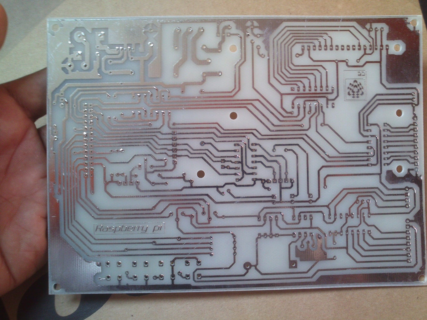
- PCB layout : single side glass epoxy PCB
- schematic and PCB tool : proteus 7.10 [3d view support]
- hand soldering
Step 6: Raspberry Pi With Add-on Board


add-on board with raspberry pi - photos
Step 7: Experiments


i2c device listing output
commands for i2c device listing
http://learn.adafruit.com/adafruits-raspberry-pi-lesson-4-gpio-setup/configuring-i2c
1, sudo nano /etc/modules
2, and add these two lines to the end of the file:
i2c-bcm2708
i2c-dev
3, sudo apt-get install i2c-tools
4, sudo nano /etc/modprobe.d/raspi-blacklist.conf
If you do not have this file then there is nothing to do, however, if you do have this file, you need to edit it and comment out the lines below:
blacklist spi-bcm2708
blacklist i2c-bcm2708
.. by putting a # in front of them.
5, sudo i2cdetect -y 1
Step 8: Video
Step 9: Downloads


- PCB bottom layer
- PCB component layout

Step 10: Reference

- www.raspberrypi.org/
- www.wiringpi.com/
- https://projects.drogon.net/raspberry-pi/wiringpi/
- www.apache.org/
- www.tomcat.apache.org
- www.nginx.org
- http://www.learn2crack.com/2013/10/setup-nginx-web...
- http://www.cyberciti.biz/faq/howto-linux-unix-crea...

Participated in the
Supercharged Contest

Participated in the
Raspberry Pi Contest


