

Introduction: Raspberry Pi Solar Weather Station


Spurred on by the completion of my two previous projects, the Compact Camera and Portable Games Console, I wanted to find a new challenge. The natural progression was an outdoor remote system...
I wanted to build a Raspberry Pi weather station that was able to sustain itself off grid and send me the results through a wireless connection, from anywhere! This project really has had its challenges, but luckily powering the Raspberry Pi is one of the main challenges that has been made easy by using the PiJuice as a power supply with it's added solar support (complete with our revolutionary PiAnywhere technology – the best way to take your Pi off the grid!).
My Initial thought was to use the fantastic AirPi module to take readings. This however, had two main drawbacks; it requires a direct internet connection to upload the results and it needs to be connected directly to the GPIO on the Pi which means it can't be exposed to the air without also exposing the Raspberry Pi (not ideal if we want this weather station to last any length of time).
The solution... build my own sensing module! Using much of the AirPi for inspiration I was able to put together a very simple prototype using a few sensor I already had; temperature, humidity, light levels and general gases. And the great thing about this is that it's really easy to add more sensors at anytime.
I decided to use a Raspberry Pi a+ mainly due to its low power consumption. To send me the results I used the EFCom Pro GPRS/GSM module, which can send a text straight to my mobile phone with the results! Pretty neat right?
I'm glad to here of any ideas you have for other great solar or portable projects. Let me know in the comments and I'll do my best to create a tutorial!
Step 1: Parts

1 x Raspberry Pi a+
1 x Sim Card
1 x Bread Board
1 x MCP3008 ADC
1 x LDR
1 x LM35 (Temperature Sensor)
1 x DHT22 (Humidity Sensor)
1 x TGS2600 General Air Quality sensor
1 x 2.2 KΩ Resistor
1 x 22 KΩ Resistor
1 x 10 KΩ Resistor
10 x Female - Female Jumper wires
Assortment of single gauge wire
1 x Single Outdoor Junction Box
1 x Double Outdoor Junction Box
Step 2: Sensing Circuit


There's quite a few different elements to this project, so it's best to do everything in steps. First off I'm going to go through how to put together the sensing circuit.
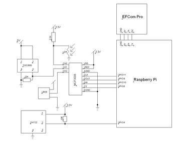
It's a good idea to build this on a bread board first, just in case you make any mistakes, I have included a circuit diagram and step by step pictures, to be referred to.
- The first component to get wired up is this MCP3008 analogue to digital converter. This can take up to 8 analogue inputs and communicates with the Raspberry Pi via SPI. With the chip facing up, and the semi-circle cut away on the end furthest from you, the pins on the right all connect to the Raspberry Pi. Connect them up as shown. If you'd like to learn a little more about how the chip works here's a great guide to the MCP3008 and the SPI protocol.
- The pins on the left are the 8 Analogue inputs, numbered 0-7 from top down. We will only use the first 3 (CH0,CH1,CH2), for the LDR, the general gas sensor (TGS2600) and the temperature sensor (LM35). First connect the the LDR as shown in the diagram. One side to ground and the other to 3.3V via a 2.2KΩ resistor and CH0.
- Next, connect the "general gas sensor". This gas sensor is used for detection of air contaminants such as hydrogen and carbon monoxide. I haven't yet worked out how to get specific concentrations, so for now the result from this sensor is a basic percentage level, where 100% is fully saturated. With the sensor facing up (pins on the underside), the pin directly to the right of the small outcrop is pin 1 and then the numbers increase clockwise around the pin. So pins 1 and 2 connect to 5V, pin 3 connects to CH1 and ground via a 22KΩ resistor and pin4 connects straight to ground.
- The final analogue sensor to connect is the LM35 temperature sensor. This has 3 pins. Take the sensor so the flat side is closest to you, the left most pin connects straight to 5V (not marked on diagram, my bad!), the centre pin connects to CH2 and the right most pin connects straight to ground. Easy!
- The last component to connect is DHT22 humidity sensor. This is a digital sensor so can be connected straight to the Raspberry Pi. Take the sensor with the grid facing you and the four pins on the underside. Pins are ordered from 1 on the left. Connect 1 to 3.3V. Pin 2 goes to GPIO4 and 3.3V via a 10KΩ resistor. Leave pin 3 disconnected and pin 4 goes straight to ground.
That's it! The test circuit's been built. I'm hoping to add more components when I have the time. I'd really like to add a pressure sensor, a wind speed sensor and I'd like to get more intelligent data on gas concentrations.
Step 3: GSM Module


Now that the sensing circuits been built, there needs to be a way of receiving the results. That's where the GSM module comes in. We're going to use it to send the results over the cellular network in an SMS, once a day.
The GSM module communicates with the Raspberry Pi via serial using UART. Here's some great info on serial communication with the Raspberry Pi. In order to take control of the Pi's serial port we need to do some configuration first.
Boot up your Raspberry Pi with a a standard Raspbian Image. Now change the file "/boot/cmdline.txt" from:
"dwc_otg.lpm_enable=0 console=ttyAMA0,115200 kgdboc=ttyAMA0,115200 console=tty1 root=/dev/mmcblk0p2 rootfstype=ext4 elevator=deadline rootwait"
to:
"dwc_otg.lpm_enable=0 console=tty1 root=/dev/mmcblk0p2 rootfstype=ext4 elevator=deadline rootwait"
by removing the underlined section of text.
Secondly, you need to edit the file "/etc/inittab", by commenting out the second line in the following section:
#Spawn a getty on Raspberry Pi serial line
T0:23:respawn:/sbin/getty -L ttyAMA0 115200 vt100"
So that it reads:
"#Spawn a getty on Raspberry Pi serial line
#T0:23:respawn:/sbin/getty -L ttyAMA0 115200 vt100"
and reboot the Pi. Now the serial port should be free to communicate with as you wish. It's time to wire up the GSM module. Take a look at the circuit diagram in the previous step and the pictures above to see how this is done. Basically, TX is connected to RX and RX is connected to TX. On the Raspberry Pi TX and RX are GPIO 14 and 15 respectively.
Now, you probably want to check that module is working, so lets try to send a text! For this you need to download Minicom. It's a program that allows you to write to the serial port. Use:
"sudo apt-get install minicom"
Once it's been installed minicom can be opened with the following command:
"minicom -b 9600 -o -D /dev/ttyAMA0"
9600 is the baud-rate and /dev/ttyAMA0 is the name of the Pi's serial port. This will open a terminal emulator in which whatever you write will appear on the serial port, i.e. be sent to the GSM module.
Insert your topped up sim card into the GSM module and press the power button. After which a blue led should come on. The GSM module uses the AT command set, here's the documentation if you're really interested. Now we check that Raspberry Pi has detected the module with the following command:
"AT"
the module should then respond with:
"OK"
Great! Then we need to configure the module to send an SMS as text rather than binary:
"AT+CMGF = 1"
again the response should be "OK". Now we write the command to send an SMS:
"AT+CMGS= "44************* "", replace the stars with your number.
The modem with respond with ">" after which you can write you message. To send the message press <CTRL-Z> . That's it, and with any luck you've just received a text straight from the your Raspberry Pi.
Well now that we know the GSM module is working you can close minicom; we wont need it for the rest of the project.
Step 4: Download the Software and Dry Run


By this stage everything should all be wired up and ready to test for a dry run. I've written a pretty simple python program that will take readings from each sensor and then send the results to your mobile phone. You can download the whole program from the PiJuice Github page. Now could also be a good time to test with the PiJuice module. It just plugs into the Raspberry Pi's GPIO, all of the wires connected to the Pi just get plugged straight into the corresponding pin outs on the PiJuice. Easy as Pi. To download the code use the command:
"git clone https://github.com/pijuice/weatherstation.git"
This is set up to send data once a day. For testing purposes this isn't great, so you might want to edit the program. This is easily done; just open up the file; "sudo nano weatherstation.py". Near the top there's a "set delay" section. Comment out the line "delay=86400" and un-comment "delay=5". Now the results will be sent once every 5 seconds. You'll also want to change the program so that it contains your own mobile number. Find where it says "+44**********" and replace the stars with your own number.
Before you run the program you will just need to download a library for reading the DHT22 humidity sensor:
"git clone https://github.com/adafruit/Adafruit_Python_DHT.git"
And the library needs to be installed:
"cd Adafruit_Python_DHT"
"sudo apt-get update"
"sudo apt-get install build-essential python-dev"
"sudo python setup.py install"
Cool, now you can test the program.
"sudo python weatherstation.py"
As the program is running the results should be sent to your mobile but also printed in the terminal every 5 seconds.
Step 5: Build the Circuit.


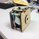
Now that everything's working in practice, it's time to build the real thing. The pictures show the general idea of how the whole unit fits together. There are two separate housing units; one for the sensing circuit (which will have holes to allow air to circulate inside) and one for the Raspberry Pi, GPRS unit and PiJuice, (completely watertight) the solar panel will be wired into the computing unit with a water tight junction. The two units can then be easily detached so that either the sensor housing or the computing housing can be removed without having to take down the whole unit. This is great if you want to add more sensors or if you need your Raspberry Pi or PiJuice for another project.
You'll need to break the protoboard to fit inside of the smaller of the two junction boxes. This is where the sensing circuit is housed. The sensing circuit is now transferred from the breadboard to the protoboard. Now you will need to do some soldering. Make sure you are comfortable with using a soldering iron safely. If you are unsure, then ask for the help of somebody who is a competent solderer.
Many thanks to Patrick in the lab over here, who saved me from making a real hash of this circuit. He managed to knock it together in a matter of minutes! If, like me, you're not the best a building circuits, and you don't have a genius like Patrick ready to help you, then you could always leave the circuit on a breadboard, as long as it fits in your electrical box.
Step 6: Preparing the Housing Units


This part is where it gets really fun. You may have noticed the rings on each box. These are designed to be knocked out so that boxes can become junctions for electrics. We'll use them to connect between the sensing unit and the computing unit, for connecting to the solar panel and also as ventilation for the sensing unit to allow air circulation.
First knock out one hole on each box for connection between the two, as seen in the pictures. Knocking out the holes can be tricky to do neatly, but a rough edge doesn't matter. I found the best method is to use a screw driver to first pierce the indented ring around each hole, and then pry it off like a paint tin lid. The waterproof cable connector is then used to connect the two boxes.
Then you'll need to make another hole in the computing housing for the solar panel wire. This is hole is then plugged with one of your semi blind cable grommets. Before you put the grommet in pierce a hole in it for the cable to go through. This needs to be as small as possible to keep it watertight, then push the micro usb end through the hole (this is the end that connect to the PiJuice).
Finally an extra hole needs to made in the sensing unit to allow air in and out. I've decided to go for the whol directly opposite the junction between the two boxes. It may be necessary to add a second hole. I guess we'll find out after some time using the weather station.
Step 7: Wiring Up and Finishing the Weather Station


Right, nearly there. The final stage is to wire everything up.
Starting with the computing unit. In this box we have the Raspberry Pi, The PiJuice which connects onto the Raspberry Pi GPIO and the GSM module which connects into the GPIO breakout on the PiJuice via female to female jumper wires. Nice and snug! at this stage I would probably advise putting some sort of sealer around entry point for the USB cable for the solar panel. Some sort of resin, or superglue would probably work.
Then move onto the sensing unit. In the photo, from top to bottom, the wires are; grey, white, purple and blue are the SPI data lines, black is ground, orange is 3.3V, red is 5V and green is GPIO 4. You will need to find jumper wires to connect to these and then feed them through the waterproof cable connector as seen in the photographs. Then each wire can be connected to the corresponding GPIO and the connector can be tightened up. At this stage it's easy to see how the design could be improved; the LDR is not going to be exposed to a great deal of light (although may still be useful to know relative values, and knocking out an extra hole might help), I think it would be better to use the same size as the computing unit box for the sensing unit also, then it would be easier to fit the circuit board into the box and there would be room to play with different arrangements.
I've put it up out in the garden now, as you can see in the photos. Hopefully in the next few days i'll be able to post some results too! And like I said earlier, if you've got any ideas for some cool projects, let me know!

Participated in the
Coded Creations


