

Introduction: Razor Scooter Underglow Double Mod (UPDATED)!


A few months ago, I dug up my Razor scooter out of the garage. I took it all apart, cleaned and lubed it, than put it back together. It looked nice and shiny, but I wanted something more. Then I saw the Let it Glow contest and had an idea. I had wanted to try a project with Electroluminescent (EL) Wire for a while at that point and now I had a use.
However, I found myself wanting something more, so I put SuperBright LEDs in the front and back of the deck to light up in front of and behind me. The final product turned out better than I had imagined!
Attachments

Step 1: Materials 1


Since this is a double modification, I will put a list of parts and tools for each separately...
UNDERGLOW:
Parts
- 3-4 ft. Standard size EL wire in the color of your choice*
- EL wire inverter/driver**
- Hot glue for attaching EL wire
- Velcro for attaching driver to scooter
-Solder
Tools
- Hot glue gun
- Electric drill with assorted bit sizes (not shown)
- Soldering iron (not shown)
*I bought my EL wire from CoolNeon. I got their "High Bright Long Life" in 2.5mm diameter in blue. It lights up the ground quite well and is very eye-catching.
**My driver is the "1 AA Driver." I powers up to 5 feet of EL wire; the Razor happens to use exactly 3 feet of wire. I bought 4 feet for good measure. All of CoolNeon's drivers come with Plug and Play connectors (male and female), copper tape, heat shrink tubing, and instructions for soldering.
Step 2: Materials 2


Now the parts for the LED mod:
Parts
- 6x 5mm High power non-diffused LEDs
- Small perforated circuit board
- 2x 9 volt batteries
- 2x 9 volt battery clips
- Small diameter single- or multi-stranded wire
- Resistor/Potentiometer for LEDs
- Solder
Tools
- Electric drill
- Soldering iron
- Wire cutters
- Dremel
- Hot glue gun
- Alan/Hex wrenches
Step 3: Underglow 1

The first part of this double mod is the underglow with EL wire. First, get your EL wire and solder it according to the instructions. If you didn't get your EL wire from CoolNeon, you can also find instructions for soldering online. The basic steps are:
1. Strip the PVC coating off the EL wire at about 3/4 in, preserving the thin corona wires.
2. Wrap a small portion of copper tape around the edge of the PVC coating.
3. Bend the corona wires back onto the copper tape and solder them on.
4. On the central copper wire, scrape the phosphor coating off as much as possible.
5. slide a small length of heat shrink tubing over the end of the wire.
6. Cut one of the wires of the Plug and Play connector shorter than the other, so they do not bend after being soldered to the contacts on the EL wire.
7. Solder each of the wires onto the contacts of the EL wire (copper tape and copper wire).
8. Slide heat shrink tubing back up and shrink it over the connection.
Once you're done soldering, plug the EL wire into the inverter and turn it on. If you soldered correctly, the EL wire should light up. If it doesn't, first put your ear up to the inverter. If you cannot hear a whining sound, it's a problem with the driver, not the wire. CAUTION: Never turn the inverter on when the EL wire is not attached. This will ruin it very quickly!
Step 4: Underglow 2


Next we will glue the EL wire to the bottom of the Razor. To prep for this, drill 2 holes in the front of the deck on the sides of the steering column. These don't have to be big, just enough for the EL wire to go through at a slight angle.
When I began gluing, I started with the heat shrunk end of the wire because I didn't want extra wire hanging off onto the ground (you can trim the normal side of the wire, but not the side with the connector). Using the hot glue gun, apply a generous amount of glue over the top and underneath the EL wire. Push it into the corner between the aluminum deck and the rectangular tube. Put the glue at the edge of the bare wire, right before the heat shrink tubing. Continue down the length of the razor. When you get to the front, thread the wire up through the hole, over to the other side, and back down through the other. Then continue gluing to the back again on the other side. You are basically making a U-turn with the EL wire. Back to front, then back again. When you come near the end in the back next to the brake, put a final big glob of glue to hold it securely, and snip the excess wire. I used hot glue for the EL wire because it holds well, but if needed, it can easily be yanked off of the Razor.
Step 5: Underglow 3


The final step for the underglow is attaching the driver. After confirming that it works with the EL wire, cut a piece of velcro off of its strip and put the hooked side on the bottom of the driver, and the fuzzy side on the back of the Razor, next to the brake. This is where the driver will sit while it is running the EL wire. You can snip it so it doesn't hang over the edge of the deck. Once the driver is attached to the deck and plugged in, you're done with the underglow portion of this Instructable! You could stop now and try to be happy with your glowing scooter, or you could go on and put crazy-cool LEDs in the front and back to make something really special...
Step 6: LEDs 1

This is the difficult half. If you're good with electronics and tools, this might be fairly easy. If you're not, this will probably be pretty hard. I was working from scratch, so it wasn't the breeziest
(as in "not a breeze") project in the world, but I got through it in about a week, including getting all the parts.
The LEDs I got were these. They are 1.7VDC, 5000 mcd orange LEDs. They are more red than orange (620nm), but they look really cool. I bought them from Jameco.
Step 7: LEDs 2


First, we'll solder the LEDs together in series using the perf board. Series splits the voltage from the power supply evenly among the six LEDs. I used 18VDC(two 9 volt batteries) and a 500k ohm potentiometer so I could change the brightness.
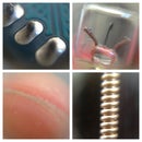
Take your perforated board and cut out 2 identical pieces out of it to fit the inside dimentions of the deck rectangular tube. To do this, take the plastic front insert out of the tube using a flat-head screwdriver. Before you cut the perf board, an word of caution: DO NOT try to cut the perf board with wire cutters! It will snap it! Instead use a Dremel or small saw. After you have your perf board pieces, put the LEDs in to the holes. Start with the center LED and then the left and right ones. Space them 3 holes apart. Before you solder them, make sure they are in series formation (see picture). Then follow the pictures and image notes for soldering.
Step 8: LEDs 3


In order to affix the LEDs and pot properly, we will need to prep the Razor again. I drilled 2 holes. One for the battery leads from the top to the inside of the deck, and another for the pot on the side of the rectangular tube. The battery lead hole just has to be big enough for the two leads to fit through, but the potentiometer's hole has to fit the threaded section of the pot so it can lock on with the included nut. While we are talking about batteries and the like, we need to solder the battery clip leads together in series (positive to negative), and a long wire to the pot output that will stretch from the front of the Razor to a little past the back for the LEDs.
Step 9: LEDs 4


We're on the home stretch! Next up is finalizing the wiring and soldering the remaining parts (The LEDs). The following is in order of events:
1. Thread the battery leads through their hole and solder the negative lead to the input of the pot and feed the output lead to the back of the scooter.
2. Solder the positive battery lead to the front LED assembly's positive input.
3. Solder a wire equal in length to the pot output to the negative lead of the front LED and feed it through to the back.
4. Remove the rear wheel and brake with the Alan wrench(es).
5. Solder the pot's output lead to the negative lead of the rear LED assembly.
6. Solder the lead from the front LED assembly to the positive lead on the rear LED assembly.
Now you should have a complete circuit. Before we hot glue the perf board to the inside of the deck and screw the pot into its place, we will test the LEDs and the pot. First, turn the resistance of the pot all the way up and plug the 9 volt batteries in to their clips. For maximum LED visibility, go into a dark room and slowly turn the resistance down. With my pot, nothing happened until I was a few notches away from minimum resistance. If your pot works with everything properly, go on to the last step!
Step 10: LEDs 5

YAY!!! Now all that's left is gluing the LED assemblies in place. When you glue, do the front assembly first, let it dry completely, then push the back assembly into place and glue it. Angle the assemblies slightly toward the ground so they light it up as you ride. After all the gluing is done and dried. Put the wheel and brake back in place. The wheel goes back on easy, but the brake could easily be a 2 person job. It requires a lot of leverage, strength, and time. However, once it's on, you're done with the project and can sit back, relax and look at the pretty colors.
Step 11: Done!!!
Step 12: V2.0 Plans


In the near future, I hope to modify another Razor scooter. Instead of EL wire, it will have adhesive LED strip lighting on the bottom of the deck. An on-off toggle will go in a new, hollow plastic insert in the front of the deck. Inside the hollow part of the insert, I will glue a 9V clip in place so I can conceal the battery and swap it out quickly. I think my new version will be much cleaner, simpler, sturdier, and easier to maintain. Please, comment, rate, and VOTE!
Third Prize in the
Let It Glow!


