

Introduction: Relief Editing


This example shows how to use some of the relief editing tools.
Functions
![]() Set Model Size - Set the real physical size of the model
Set Model Size - Set the real physical size of the model
![]() Smooth Relief - Apply smoothing filter to the whole relief or a specific area
Smooth Relief - Apply smoothing filter to the whole relief or a specific area
![]() Texture Relief - Apply 3D texture to the whole relief or a specific area
Texture Relief - Apply 3D texture to the whole relief or a specific area
![]() Scale Relief Height - Scale relief heights in Z
Scale Relief Height - Scale relief heights in Z
![]() Smooth Sculpting - Interactive Sculpting tool to smooth areas of the relief
Smooth Sculpting - Interactive Sculpting tool to smooth areas of the relief
![]() Smudge Sculpting - Interactive Sculpting tool to re-model relief like clay
Smudge Sculpting - Interactive Sculpting tool to re-model relief like clay
![]() Deposit Sculpting - Interactive Sculpting tool to add material to the relief
Deposit Sculpting - Interactive Sculpting tool to add material to the relief
![]() Carve Sculpting - Interactive Sculpting tool to remove material from the relief
Carve Sculpting - Interactive Sculpting tool to remove material from the relief
![]() Envelope Distortion - Select a floating blue relief clipart to copy, distort, and paste it along a curve
Envelope Distortion - Select a floating blue relief clipart to copy, distort, and paste it along a curve
The following can be managed from the Relief Layers section.
![]() Add a new Relief Layer to the model
Add a new Relief Layer to the model
![]() Import a new Relief Layer from a file
Import a new Relief Layer from a file
![]() Export the selected/highlighted Relief Layer
Export the selected/highlighted Relief Layer
![]() Duplicate the selected Relief Layer
Duplicate the selected Relief Layer
![]() Transfer the selected Relief layer to the opposite side (Back Relief Layer)
Transfer the selected Relief layer to the opposite side (Back Relief Layer)
![]() Create a new Bitmap Layer from the selected Relief Layer
Create a new Bitmap Layer from the selected Relief Layer
![]() Delete the selected Relief Layer from the model
Delete the selected Relief Layer from the model
![]() Merge (combine) the visible layers to form a new Relief Layer
Merge (combine) the visible layers to form a new Relief Layer
Step 1: Example 6-1
Attachments

Step 2: Example 6-2
Step 3: Texture From Image Tutorial
1Open Model - stone_pattern.png
- Width = 12”

2 Select the stone_pattern Bitmap Layers in the Project Tree
3Create Relief Layer (from bitmap layers) ![]()
- New Height = 0.15”
4Smooth Relief - 1 pass
Next you are ready to save your new texture by into your clipart folder
5 Open Relief Clipart Library
- Chose to view the Custom Reliefs clipart folder
- Using your left mouse button select in your project tree, stone pattern Relief Layer you have just created
- And drag into the Relief Clipart Library

Attachments
Step 4: Relief Layer Badge Tutorial
1 Open Model Relief Layer Badge.art
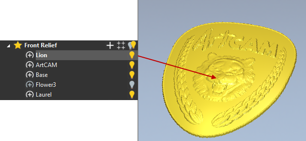
2 Expand the Front Relief Layers section of the Project Tree

3Hide all Relief Layers by clicking on the twin light bulb![]() next to the main branch Front Relief
next to the main branch Front Relief
To better understand layers, use the light bulbs to hide and show different relief layers. This will help demonstrate how they interact together. Hide all the layers when finished
4 In the Project Tree, click on the light bulb ![]() to show the Laurel Relief Layer and the Flower3 Relief Layer
to show the Laurel Relief Layer and the Flower3 Relief Layer
5 Show the Base Relief Layer and note how it embosses the other reliefs
6 Show the ArtCAM Relief Layer to finally display the text
As demonstrated, a Relief Layer can be switched on/off as required by clicking the adjacent light bulb icon. Any Relief operations assigned to a Relief Layer that is switched off will be temporarily hidden from the model.

7Hide the Base Relief Layer to see the result


8Toggle the Base layer back on but Hide the Flower3 Relief Layer
9 Make the ArtCAM Relief Layer active by clicking on its name to highlight it.

10 Select New Relief Layer![]() from the lower Project Panel.
from the lower Project Panel.
The new Relief Layer is created directly above the active Relief Layer.
11 Select the new Relief layer and rename it to Lion from the lower Project Panel

12 From the Relief pull down menu, chose Import, followed by Import to load in an existing relief ![]()
13 Choose Lionhead.rlf from the ArtCAM data folder
14 No changes are required so Click Paste on the Transform form
Relief Layers can be utilised to organise work, simplify adjustments, and easily experiment with different variations.
15 Create another New Relief Layer and rename it to Banner.
16Open the Relief Clipart Library from the Relief creation toolbar ![]()
- In the pull down list at the top, choose the Banners Library.
- Click on Banner1 to select and import it

17 Use the Transform tools to resize and position it suitably or use the parameters suggested below.
- Press F9 to centre in the model
- In Scale and Size, enter a new Scale of 50% with all sizes linked then click Apply
- In Origin position, Enter a value of 2 in Y and then Apply (note ArtCAM model is in imperial units)
18 At the top of the Form, Click on More Options icon ![]()
- For now, ignore the Paste Combine Mode but enter a value of 0.1 for Height (start height).
- Select Paste.
The banner appears to be sitting overlapped with the rest of shield. This can be changed by adjusting the Relief Layer Combine mode. The Combine mode dictates how the Relief Layers interact with each other. Currently all the Relief Layers are on the Add Combine mode. If the problem layer, in this case, the new banner layer is changed from Add to Merge High, it will blend in with the relief of the design.

19 Make sure the Banner Relief layer is active
20 In the lower parameters section on the Project panel, change the Combine mode from Add to Merge High

The banner now blends in with all the other Relief Layers.
The Relief layers are effective from top to bottom. The Combine mode of the top Relief Layer affects everything below it. The Combine mode of the bottom Relief layer affects nothing.

Step 5: Grapevine Tutorial
A customer has asked us to reproduce an existing molding. He has indicated to us that it doesn’t need to be an exact duplicate, but if the end results produced in ArtCAM were similar to the original, then that would be fine.

Getting the Design into ArtCAM
There are several different ways that an ArtCAM user could go about getting the design vectors into the software.
The first method, the designer would visually inspect the piece of moulding and with part in hand would build the vectors in ArtCAM by eye. This is actually the way that the vectors we will be using have been created.
A second method to get this data into ArtCAM could be, to take a digital photograph of the moulding and use it as a template. The photo could be opened in ArtCAM and the user could trace the necessary outline vectors. This method may be a bit easier for someone who may not be very artistic. Using a digital photo would give the user the ability to follow the outlines of the picture and basically trace it.
The third possibility could be to use the plastic transparency sheet on the Wacom Pressure sensitive tablet and manually trace the outline of a printed photograph. This option is similar to the second method but may apply more to someone who may not have the image in digital format. If it was a small 5” X 7” photo it could be blown up in size before it was used for tracing, this is of course providing the size of the photo stays within the limits of the Wacom tablet’s transparency envelope.
Analysing the Design Vectors of the Grapevine
If you look and see how the designer of this file has set up the design vectors you should notice a few things.

The vectors for each modelling section are on separate layers, making it much easier to work with.
You can see that there are several separate vector entities that represent the different branches of this vine. These parts of the vine have been separated out so that there is a certain effect achieved when the vine is built. If these areas were all combined into one main branch then the results of building the vine shape would not look natural or organic. What would end up happening is the large common area where the main vine and the smaller vine meet up would have a very balloon like and bubbly appearance. The only way that a user would know this information would be from trial and error and/or from experience. Having the small branches of this vine set up the way they are is going to give us the most natural looking effects possible with the least amount of relief modelling effort. ArtCAM contains useful tools that we can use to go in and alter these areas to look more natural after we have built them into 3D.
If you select the circular vectors representing the grapes, you will notice that they have not all been grouped together as one entity. Random diameter circles within the bunch have been grouped together in order to give the relief of the grapes a varying effect. This varying effect for the grapes is achieved by the difference in the diameter of the various circular vectors.
The way it has been set up is that the different groups have been assigned unique characteristics for relief modelling and since the circles have varying diameters they will individually reach unique heights. The way that ArtCAM works is, when using the Shape Editor to build reliefs the software associates width with height, therefore the wider something is the higher that it is going to have to be in 3D space so that it looks proportional.
The leaf has two design vectors showing the shape, there are other vectors on another layer that will be used to achieve an underlying sweep.
One last detail to pay attention to in this design is the resolution. Resolution is a very important factor of an ArtCAM job. The resolution is set at 1991 X 663 pixels; normally the rule of thumb (depending on job sizes and relief modelling technique) is that the shortest side of the model should contain approximately 1000 pixels. Having said this you can see that the shortest side of this job only contains 663 pixels. The reason for this is that the entire piece is going to be modelled using vector modelling. When you are doing vector modelling it is possible to work with a resolution that is approximately 1/3 less than what you would normally use if you were colour modelling. The 1000 pixel rule outline above is for colour modelling so that is why you are seeing a lower resolution then normally recommended.
Strategy for Building the Grapevine
As with most projects it is important that before you begin to work that you think about how you are going to get to the final result. The same rules apply to ArtCAM, before we start to build our relief, we should take a few minutes to look at it and think about the best way to build our design into a 3D relief.
As in many cases with ArtCAM, when you are going to be building a design that contains several parts or pieces, it is best to try and isolate the smaller parts and build these in separate relief layers.
For the Grapevine the plan is going to be as follows:
- Create three different relief layers for Grape Leaf, Main Vine and Grapes and construct them in individual relief layer.
- Build the leaf is several steps. Since the Shape Editor is not going to give us enough control over how the shape is built, the designer has decided to utilize one of the more user definable relief modelling tools; Extrude.
- The extrusion function will be used to build the underlying shape of the leaf.
- Build up the vine shape using the main vine vector as well as the branch vectors.
- Since the piece needs to look as natural and organic as possible we will have to do some sculpting on certain areas of the relief.
- The third relief that is going to be built will be the grapes. The grapes should be quite straightforward and easy to build since we will just use the Shape Editor to build the shapes.
- Once building the individual relief is done all the layers will be made visible.
Building the Grapevine
1 Open the file Grape-Vine.art
This tutorial is based in the default ArtCAM function layout. If you have customised your layout and wish to return to the standard, from the Window pull down menu choose Reset Layout.
2 Toggle Vector Visibility to on to show vectors in the 3D View
Grape Leaf

1 From the Project Tree, show the Leaf and Construction Vector Layers, hide all other Vector Layers
2 Make 3D Leaf the active Relief Layer
The Leaf layer contains the vector representing the size and shape of the leaf.
The Construction layer has additional vectors used to assist us in building the underlining relief.
3 Open the Extrude function from the flyout toolbar located on the Relief Creation toolbar
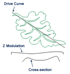
4 In the model area pick the straight vector that runs through the leaf for the drive curve and click Select button in the panel next to Drive curve
5 Check the Use as centreline box
6 Pick the vector that represents the profile (Cross-Section) for this extrusion, click the Select button next to Start Profile
7 Check the Invert curve in Z box to make sure that the hash marks are on the inside of this vector shape
8 Pick the vector that represents the Z modulation and click the Select button next to Z Modulation
9 Make sure that Add is the option that is selected and then click the Apply button to build the underlying shape of the Grape Leaf
10 Close the Extrude panel
Notice that the underlying shape for this leaf that has been extruded is larger than the actual leaf itself. This is a pretty common technique used for relief modelling in ArtCAM where the underlying shape is created much larger than needed and then the required area gets trimmed out.
11 Select the vector outline of the leaf and press the Zero Outside Vector function
This should trim out the shape of your leaf.
12 With the leaf outline vector still selected, press F12 to open the Shape Editor
13 Click Add in the Shape Editor window then Close
- Dome, Angle=-5º, Start Height=1mm (0.04”), Apply
This will add the concave shape of -5º with a small start height to the leaf. You will not see much of a change when the vector attributes are added to the existing relief. The leaf will get a bit higher and it will also provide a bit more of a dish shape to the leaf. By doing this we are trying to add a more natural look.
14 Select the vectors that represent the vein detail for the leaf
15 Press F12 to open the Shape Editor
- Add Dome, Angle= -25º, Start Height= -0.5 mm (-0.02”) , Apply
16 In the Project Tree, click on the light bulb next to 3D Leaf to hidethe 3D Leaf Relief Layer
Main Vine

1 Make 3D Vines the active Relief Layer
2 Show the Vines Vector Layer, hide all other Vector Layers
3 Select the vine vectors one by one, open the Shape Editor with F12 and Add or Merge high. The values are already applied to the vector shape;
- Main vine (Dome 68º, Start Height=1mm (0.05”), Add), Apply
- 1st and 2ndbranch (Dome 83º, Start Height 1mm (0.04”), Merge High), Apply
- 3rdbranch (Dome 70º, Start Height=1mm (0.04”), Merge High), Apply
- 4thbranch (Dome 83º, Start Height=1mm (0.04”), Merge High), Apply
- 5thbranch (Dome 70º, Start Height=1mm (0.04”),Merge High), Apply
Observe the creases in the areas where the branches have been merged into the main vine. Ideally, we want to smooth these areas in order to make the vine look more organic.
4 Zoom into the first area where you can see the creases
5 Activate the Smooth Sculpting tool
6 In the Tool Setting Panel, set the following:
- Radius = 25
- Strength = 50
- Smoothness = 100
In the Mask area, check the Material SafetyPlane and enter in a value of .025mm (0.01”)
By making adjustments to the Mask section of the Sculpting panel, we ensure that when we are smoothing the relief, the smooth tool will not affect the background (zero plane), causing a radius at the edge where the relief meets the zero plane.
7 While using the Smooth tool, vary the diameter and strength of this tool accordingly to achieve the desired results
8 Smooth the creases where the smaller branches attach to the larger branch
Basically we just want to get rid of the creases and make the vine look more natural. Individual results may vary.
To zoom in & out you need to hold the Alt key down while using the mouse as you would in a regular 3D view, or use the icons at the top of the screen.
9 Click on the light bulb next to 3D Vines to hide the 3D Vines Relief Layer
Grapes
1 Make 3D Grapes the active Relief Layer
2 Show the Grapes Vector Layer, hide all other layers
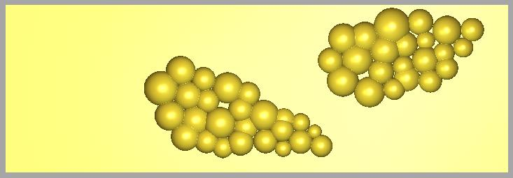
3 Select the different groups of circles that represent the grapes and use the Shape Editor to build these shapes and use Merge Highest. The values are already applied to the vector shape;
- 1st set (Dome 86º, Start Height= 3 mm (0.13”), Merge High), Apply
- 2nd set (Dome 80º, Start Height= 2 mm (0.11”), Merge High) , Apply
- 3rd set (Dome 89º, Start Height= 1 mm (0.06”), Merge High) , Apply
- 4th set (Dome 68º, Start Height= 2 mm (0.10”), Merge High) , Apply
Use the Merge High option so that the grapes are blended into one another.
It can be useful to use the preview Relief Layer function if working from the 2D view to track the progress of your relief in the 2D view. Doing this will display an interactive greyscale of the areas as they built.
Viewing Combined Reliefs
Now that we have built all of the pieces for our finished part we can now bring them all together.

4Show all Relief Layers
5Toggle Vector Visibility to hide the vectors in the 3D View ![]()
6 Save the finished ArtCAM files as Finished Grape Vine.art
The design is now complete and ready for machining.


