

Introduction: Remote Controlled Car Using Arduino With Obstacle Avoiding
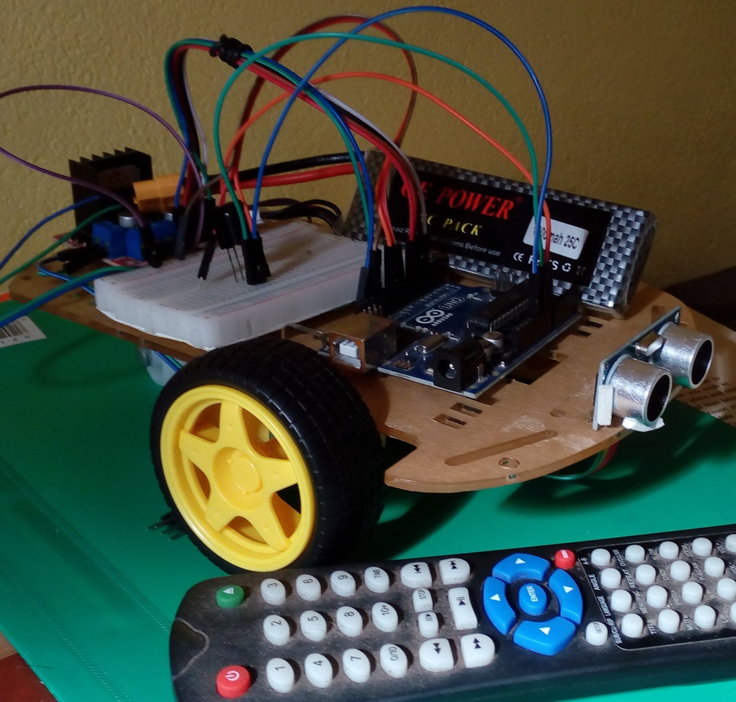


Here i'm going to instruct you on making a robot car which can be controlled by an IR remote controller. This robot car can be controlled by our usual TV remote or you can use any other IR remotes as well. Most special thing with this robot car is, it has the self obstacle avoiding function. When you drive this car using your TV remote or other IR remote, it will stop automatically whenever it met an obstacle while it moving forward. I hope to do step by step guide on making this robot in very easy way.
Step 1: Required Components for This Project


- Arduino UNO - https://www.ebay.com/p/Arduino-UNO-R3-Board-With-...
- Smart robot car chassis with (2 x) toy car wheels and (1 x) Universal wheel (or ball casters) - https://www.ebay.com/itm/Motor-New-Smart-Robot-Ca...
- Two DC motors - https://www.ebay.com/itm/Arduino-Smart-Car-Robot-...
- L298n motor driver - https://www.ebay.com/itm/New-L298N-DC-Stepper-Mot...
- HC-SR04 Ultrasonic Sonar sensor - https://www.ebay.com/itm/Ultrasonic-HC-SR04-HC-SR...
- TSOP1738 IR receiver - https://www.ebay.com/itm/3-Stuck-IR-Empfanger-TSOP...
- 7.4V 1300mah Lipo battery - https://www.ebay.com/itm/VOK-Lipo-Battery-for-RC-...
- TV remote
Jumper wires (male-to-male, male-to-female)
Mini breadboard
Ultrasonic sonar sensor mounting bracket
Screws and nuts
Screwdriver
Soldering iron
Double sided tape(optional)
Hot glue gun(optional)
Step 2: Download the IRremote Library and NewPing Library
- Download the RobotIRremote.rar file
- Unrar the file and copy RobotIRremote file
- Paste the file in Arduino libraries folder where you have installed the Arduino software in your PC (e.g:-C:\Arduino\libraries)
NewPing library
- Download the NewPing.rar file
- Unrar the file and copy NewPing file
- Paste the file in Arduino libraries folder where you have installed the Arduino software in your PC (e.g:-C:\Arduino\libraries)
Attachments

Step 3: Obtaining Hexadecimal Numbers of the TV Remote Keys


Before build the robot, we have to obtain the hexadecimal numbers of respective TV remote keys. These keys will be used for move the robot car forward, backward, left and right. Please follow the below steps:
- Wire the Arduino UNO and TSOP1738 as shown in the above circuit diagram. You can power the arduino UNO by PC via a USB cable (No need batteries).
- Download IR_hexa_number_receive.ino
- Upload the code to arduino UNO board
- Open the serial monitor window
- Press any key in TV remote, you would like to use as Robot move forward key
- Press any key in TV remote, you would like to use as Robot move backward key
- Press any key in TV remote, you would like to use as Robot move left key
- Press any key in TV remote, you would like to use as Robot move right key
- Press any key in TV remote, you would like to use as Robot STOP key
In my case, I got the following hexadecimal numbers. You will have different numbers from your remote
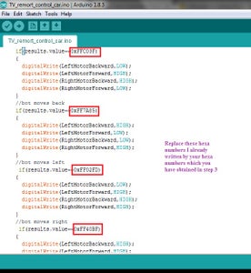
UP Arrow Key = move forward = 0xFFC03F
DOWN Arrow key = move backward = 0xFF7A85
LEFT Arrow key = move left = 0xFF02FD
RIGHT Arrow key = move right = 0xFF40BF
ENTER key = robot STOP = 0xFFFA05
Note: In the serial monitor, you only get values like FFC03F.... and you have to add 0x to the front of FFC03F and write it as 0xFFC03F when you write these values in your code later.
In some cases, you will receive value like FFFFFF in between your hexadecimal numbers in your serial monitor, just ignore them.
important: copy and save the hexadecimal numbers you have obtained to a Notepad, you will need these numbers when you are coding the robot.
Attachments
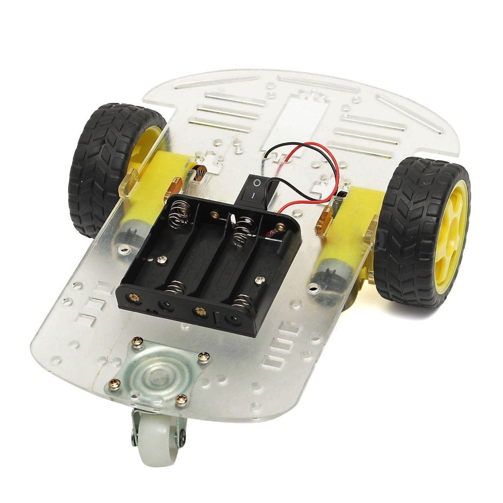
Step 4: Build the Chassis


Solder two wires to each DC motor. Then fix two motors to the chassis using the screws. If you need any clarification, please watch this youtube video and it will show you how to assemble the Smart 2WD Robot car chassis. Finally attach the Universal wheel (or ball caster wheel) to the back of the chassis.
Step 5: Mount the Components
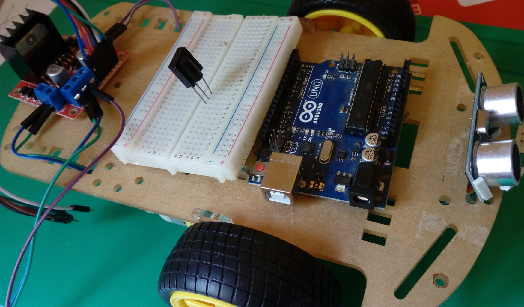
Mount the Arduino UNO, L298n motor driver, Ultrasonic sensor and TSOP1738 containing breadboard on the chassis. Note: when mounting the arduino board, leave enough space to plug the USB cable, since later you have to program the arduino board by connecting it to the PC via a USB cable.
Step 6: Make Wire Connections
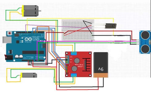


L298n motor driver:
+12V → Lipo battery (+)
GND → Lipo battery (- ) important:connect the GND to lipo battery (-) and to arduino board any GND pin
+5V → arduino Vin
In1 → arduino digital pin 7
In2 → arduino digital pin 6
In3 → arduino digital pin 5
In4 → arduino digital pin 4
OUT1 → Motor 1
OUT2 → Motor 1
OUT3 → Motor 2
OUT4 → Motor 2
Breadboard:
Connect two jumper wires to arduino board 5V and GND pins, then connect both wires to breadboard. now you can use this as +5V supply.
TSOP1738:
GND (Left most pin) → breadboard GND line
Vs (middle pin) → breadboard +5V line
OUT (right most pin) → arduino digital pin 11
HC-SR04 Ultrasonic Sonar sensor:
VCC → breadboard +5V
Trig → arduino analog pin 1
Echo → arduino analog pin 2
GND → breadboard GND
Step 7: Programming the Arduino UNO
- Download TV_remote_control_car.ino
- Open the code
- Replace already written 5 hexadecimal numbers in the code by your hexadecimal numbers that you obtained in the Step 3, saved in Notepad.
- Upload the code to Arduino UNO via a USB cable
Attachments
Step 8: Make Battery Connections

Connect the Lipo battery to the L298n motor driver as follows:
Lipo battery (+) → +12V
Lipo battery (- ) → GND
Step 9: Great !!!
Now you have your own remote control car
I would be happy to answer any questions you have
email me: dnayantha88@gmail.com
search me on facebook and linkedin for more projects - Danusha nayantha
Thank You

Participated in the
Remote Control Contest 2017

Participated in the
Wheels Contest 2017

Participated in the
Arduino Contest 2017


