

Introduction: Rotary Encoder LED Strip Brightness Controller


Simply LED strip brightness controller with rotary encoder and attiny 85 microcontroller
Step 1: Intro:
I will show you how to easily control brightness of LED strip. This is actually a PWM controller. It is designed only for DC. Forget AC and high voltage. Let's start...
Step 2: Parts:
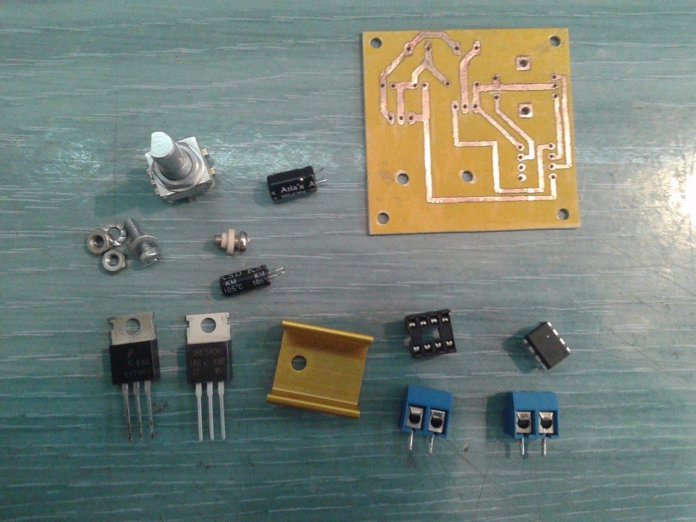

For this project you need:
1. Attiny 85 + socket
2. Rotary Encoder (http://www.ebay.com/itm/12mm-Rotary-Encoder-Push-B...
3. 7805 voltage regulator
4. 100uF electrolytic capacitor
5. 10uF electrolytic capacitor
6 IRF540 N-Channel MOSFET Transistor + heatshink
7 Two Terminal Blocks
Step 3: Rotary Encoder Theory

If you have ever thought that resistors going with encoders forget it this time. With a rotary encoder we have two square wave outputs (A and B) which are 90 degrees out of phase with each other. The number of pulses or steps generated per complete turn varies. The diagram below shows how the phases A and B relate to each other when the encoder is turned clockwise or counter clockwise.
Every time the A signal pulse goes from positive to zero, we read the value of the B pulse. We see that when the encoder is turned clockwise the B pulse is always positive. When the encoder is turned counter-clockwise the B pulse is negative. By testing both outputs with a microcontroller we can determine the direction of turn and by counting the number of A pulses how far it has turned. Indeed, we could go one stage further and count the frequency of the pulses to determine how fast it is being turned. We can see that the rotary encoder has a lot of advantages over a potentiometer.
Step 4: Rotary Encoder + Arduino

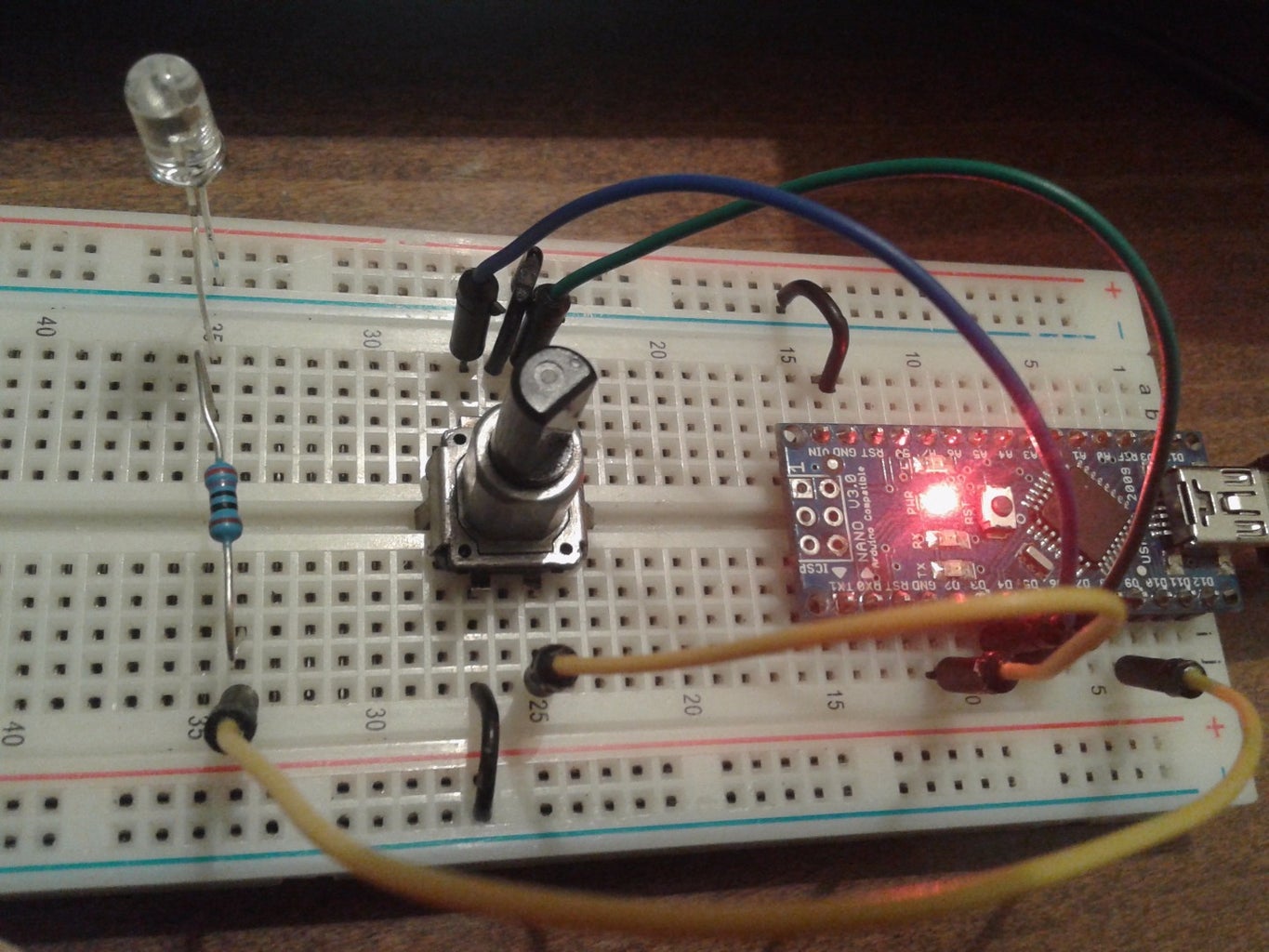


Connect the wires as shown in pictures and test circuit on arduino. Use any PWM output.
Here is the code:
//
int brightness;
unsigned long currentTime;
unsigned long loopTime;
const int pin_A = 2;
const int pin_B = 3;
int buttonPin = 4;
const int ledPin = 9;
unsigned char encoder_A;
unsigned char encoder_B;
unsigned char encoder_A_prev=0;
boolean lastButton = HIGH;
boolean currentButton = HIGH;
void setup(){
pinMode(ledPin, OUTPUT);
pinMode(pin_A, INPUT_PULLUP);
pinMode(pin_B, INPUT_PULLUP);
pinMode(buttonPin, INPUT_PULLUP);
currentTime = millis();
loopTime = currentTime;
}
boolean debounce(boolean last)
{
boolean current = digitalRead(buttonPin); if (last != current) { delay(5); current = digitalRead(buttonPin); } return current; }
void loop(){
currentButton = debounce(lastButton);
if (lastButton == HIGH && currentButton == LOW)
{
brightness = brightness + 255;
}
lastButton = currentButton;
if(brightness > 255) brightness = 0;
currentTime = millis();
if(currentTime >= (loopTime + 5))
{
encoder_A = digitalRead(pin_A);
encoder_B = digitalRead(pin_B);
if((!encoder_A) && (encoder_A_prev))
{
if(encoder_B)
{
if(brightness + 5 <= 255) brightness += 5;
}
else
{
if(brightness - 5 >= 0)brightness -= 5;
}
}
encoder_A_prev = encoder_A;
analogWrite(ledPin, brightness);
loopTime = currentTime;
}
}
//
Step 5: Uploading Code on Attiny 85
If you know how to do this its great. If you don`t know how to do this find tutorial on internet...
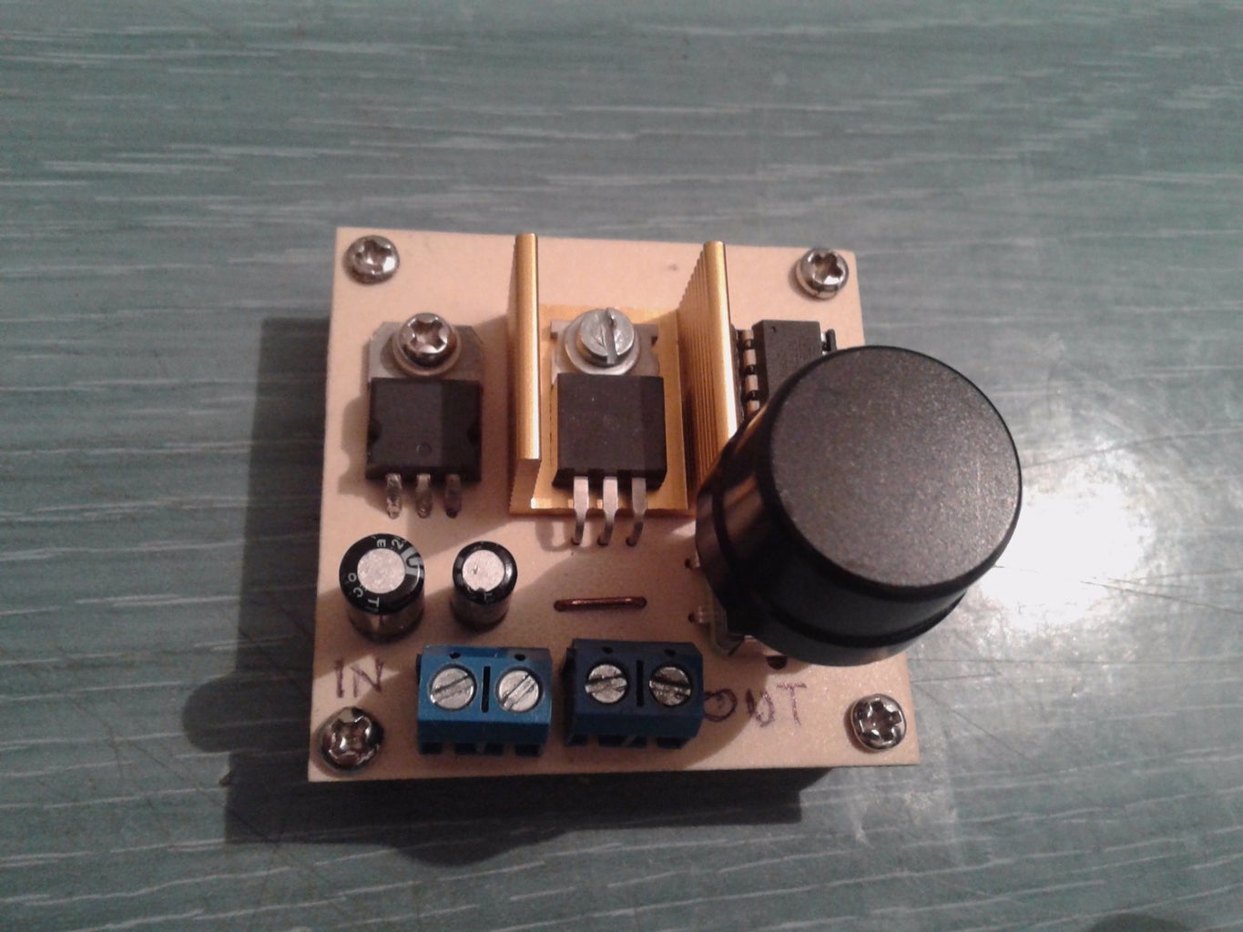
Step 6: Rotary Encoder + Attiny 85
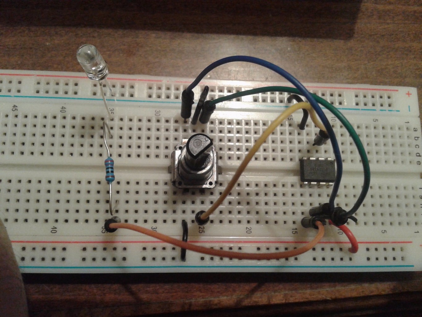

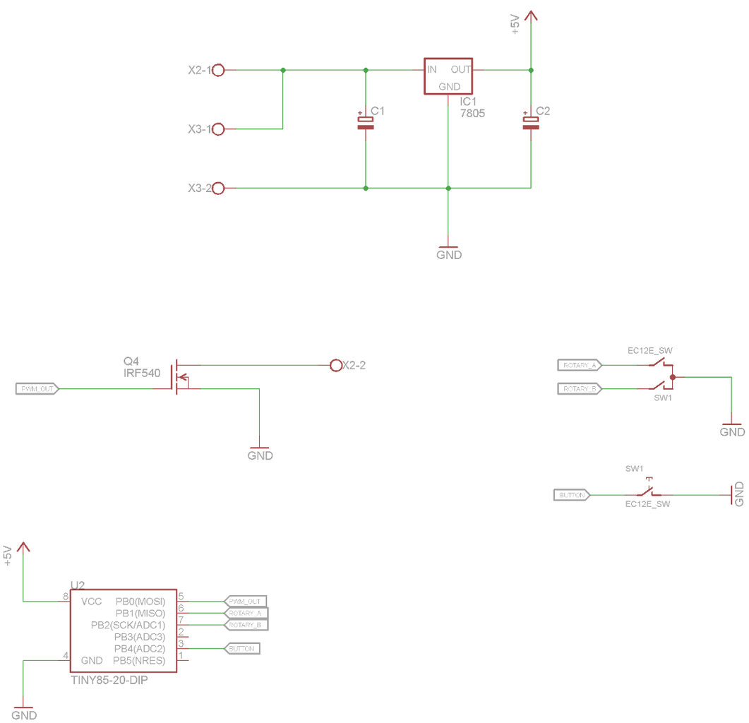

Upload the same code as before but change inputs and outputs. I desinged a PCB of the Eagle, and if you want to make the PCB, you must use the following inputs and outputs
led pin on 0( attiny pin 5)
rotary encoder pin A on 1(attiny pin 6)
rotary encoder pin Bon 2(attiny pin 7)
button on pin 4 (attiny pin 3)


