

Introduction: STM32F103 Timer Interrupt (using Keil and STMCubeMX)


![STM32103: esp8266 NodeMCU ThingSpeak [using mbed.h]](https://content.instructables.com/FIN/4MND/IIEYTJZ0/FIN4MNDIIEYTJZ0.jpg?auto=webp&crop=1%3A1&frame=1&width=130)
![STM32F103: esp8266 nodeMCU Getting Started [using mbed.h]](https://content.instructables.com/F2V/D3SJ/IIDJE6ZX/F2VD3SJIIDJE6ZX.png?auto=webp&crop=1%3A1&frame=1&width=130)
In this tutorial, I will demonstrate the use of interrupts with timers.
The interrupt is simply used to toggle the LED on our STM32 Board.
This tutorial is divided into three steps:
Step 1: Creating Project In STM32CubeMX
Step 2: Programming in Keil
Step 3: Visualizing Output
Step 1: Creating Project in STM32CubeMX


Open STM32CubeMX. Click on ‘New Project’. From Series Select ‘STMF1’, from ‘lines’ select STM32F103. From MCUs list, select ‘STM32F103RBTx’. Click “OK”.
[1]
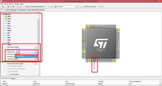
Now, 2 things need to be done. First, on the STM32 microcontroller being shown in your STM32 Board, Click on ‘PA5’ and select ‘GPIO_Output’. Second, Select ‘Internal Clock’ as ‘Clock Source’ under the ‘TIM1’ tab under the Peripherals tab as shown in figure:
[2]
Now, Switch to Configuration Tab. There under ‘Controls’ you will see a ‘TIM1’ Button. Click on that and you will see a window like this:
[3]
Now, in this “Parameter Settings” tab (already selected) under counter settings Select ‘Prescaler (PSC – 16 bits value)’. And in front of that you will see a drop down arrow (at a place indicated by red arrow in following figure), Click on that. Make sure that “Decimal” is selected. And Change its value from ‘0’ to ‘64000’.
[4]
Change counter Mode to ‘Down’. Again, select Counter Period, click on that drop down arrow in front of that and make sure that ‘Decimal’ is selected. Now, Change its value to 1. Your window must look like this:
[5]
Click “Apply” and then click “OK”.
Now, under ‘System’ tab click on ‘GPIO’ Button. Select ‘PA5’ and in ‘User Label’ type “Ld2”.
Now, Under ‘System’ tab click on ‘NVIC’ Button. Select ‘TIM1 break Interrupt’ from interrupt table, enable it and set Preemption Priority to ‘1’. Do the same for ‘TIM update interrupt’. And thus now your window should look like this:
[6]
Now, Click on ‘Generate Code’ button. Fil in Project Name, Where to save Project and ‘Toolchain / IDE’ select ‘MDK-ARM V5’. Then Click “OK”. And Then Click “Open Project”.
Step 2: Programming in Keil


Once Project is Open in Keil, Open ‘main.c’ located under ‘Application/User’ Folder, located under ‘Project:<projectName>’. Scroll down to find While(1). Just before While(1) add this line of code:
HAL_TIM_Base_Start_IT(&htim1); //start timer1 in interrupt mode.
And your Keil Window will look like:
[7]
Now, Open ‘STM32Fxx_it.c’ in vicinity of ‘main.c’ file. Scroll down to find ‘TIM1_UP_IRQHandler’ function.
In their write following lines of code:
static uint32_t counter = 0;
if (counter >= 500)
{ HAL_GPIO_TogglePin(LD2_GPIO_Port, LD2_Pin); counter = 0; } counter++;
And thus your window will look like this:
[8]
Click on ‘Build’ Button (or Press ‘F7’). The Connect your STM32 Board and Click on ‘LOAD’ button (or Press ‘F8’)
Step 3: Visualizing Output
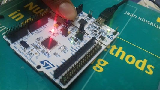
Now, Press the ‘Black’ Rest button on you ‘STM32’ Board.
Your see LED toggling itself ON and OFF after some interval.


