

Introduction: Self Balancing Arduino-Based Robot

Hello,
The idea behind this project is to build a simple Arduino-based self-balancing robot.
There are plenty of tutorials but most of them use really messy code or external libraries. The point of this tutorial is to understand how such a robot works and be able to make one for yourself.
Step 1: Understanding the Basics
The physics behind the self balancing robot are similar with an inverse pendulum. At any point in time you need to calculate the tilt angle and move your robot wheels in the other direction trying to keep the tilt angle at 0. You can imagine the same principle when you're trying to balance a broom at the top of your finger.
Step 2: Gather the Hardware You Will Need the Following Components:


- Arduino nano x 1
- DRV8833 x 1
- MPU6050 x 1
- Reduction Gears with dc motors x 2
- AA 1.5V battery x 4
- 9V battery x 1
- 9V holster x 1
- 4xAA holster x 1
- female pcb header x 54
- 7x5cm pcb x 1
- switch x 1
Step 3: Controlling the Motors


To be able to move our robot we need to use the DRV8833 which is a double H-bridge. You can build one for yourself using MOSFETs but that will increase the chance to make faulty soldering.
To understand how an H-bridge works we can look at the following schematic.
Depending on which 2 opposite gates(MOSFETS) we close we can change the way the current is flowing through the motor thus change it's rotational direction.
Now how about we control the wheel's speed? We can open and close a pair of gates with different speeds. Because of it's current inertia the motor won't stop immediately. We can achieve this via a so called Pulse Width Modulation Signal, or simply a PWM. Depending on the Duty cycle ( or the width of one period of the signal when the value is on HIGH) we can set a higher or lower speed.
In our case on the board DRV8833 In1 and In2 are the pins that control the pair of gates. Out1 and Out2 are the output pins that connects directly to the motor pins. Since the DRV8833 is a dual H-bridge there are 4 In pins (InA1, InA2, InB1, InB2) and 4 outputs(OutA1, OutA2, OutB1, OutB2). They are grouped by the letter so all pins with A stands for the first H-bridge, while the pins with B stands for the second H-bridge.
For example if we want to set the motors to go forward with half of the full speed of the motors we could apply 2 PWM in InA1 and InB1 with a duty cycle of 50% while in InA2 and InB2 we will connect ground.
Step 4: Reading the Tilt Angle
For our project we used an MPU6050 which is a 3 axis accelerometer and gyro. The sensor itself can measure the angle of tilt and as well the speed that the sensor is moving in each axis. We can calculate the tilt angle from both components each one with it's own good and bad points.
The problem with the gyro angle is that in time in drifts. What the means is that if we keep the sensor still after some random time the measure that it's measuring will increase or decrease constantly.
On the other hand the accelerometer angle is really accurate in time, but it's really noisy.
Therefore we must combine both of these 2 components in a so called Complementary Filter
The trick is that this filter apply a low pass filter over the accelerometer value and a high pass filter over the gyro angle, that way, the acc angle has it's noise removed and the gyro has it's own long time drift compensated.
The formula for the complementary filter looks more or less like this
Angle = α * (prev.Angle + gyro.Angle) + (1-α) * acc.Angle<br>
A pretty common value for α is around 0.98
Step 5: Projecting a Regulator
Even though you're not familiar with control theory I will do my best to explain what we are trying to achieve with this "thing" called a regulator.
Let's think for a second. When our robot tilt in one direction we want to power the motors in that direction so it can compensate the tilt in the other direction.
So for the start we can check if the value of it's angle is >0 or <0 ( let's say positive values are forward tilt and negative values are backward tilt) and depending on that we power the motors in that direction. For example if we measure a value of -15 it means that the robot is tilted 15 degrees backward so we want to power the wheels to go backwards.
Now the question is how fast the wheels should spin? For start we can full power them, but you will see that the robot in the best case scenario it will compensate the first tilt but because it tilt so hard in the new direction it won't be able to compensate that
So how about we make the speed Proportional with the angle? Well that sound cool but how can we can convert angles into speed? What about percentage?
We know for sure that our robot can tilt from -90 to +90 , and we also know that our motors can run with signals from 0 to 255(100% duty cycle). So what we need right now is 2 thing:
- Find in what direction the robot is tilted
- Convert the angle into speed
For step 1. it is quite simple. We just check the sign of the angle. If the angle is >0 then the robot is tilting forward otherwise it is tilting backwards.
For step 2. it's a bit tricky but we can solve it with math. We need to map a value from the interval [0:90] ( the absolute value of the angle) to [0:255] That being said it will look something like this
val.Map = floor(abs(angle) * 255/90)
It is mandatory to make the value floored since when you create a PWM signal you must apply an integer value for the duty cycle.
So far so good, we can control the speed of the wheel based on the calculated angle more or less. I say more or less because right now the Proportion between the angle and the speed is 1. There is no constant that can affect this ratio. What about adding one?
so the speed is
proportional.speed = Kp*val.Map
but as i said earlier the maximum value for the duty cycle must be 255. Therefore we must check if proportional.speed is greater than 255 then make it 255
proportional.speed = Kp*val.Map;
if(proportional.speed > 255) proportional.speed = 255;
What we just did is called an P-regulator, where P stands for Proportional
In theory such regulator well tuned(Kp constant) should be able to keep the robot balanced for a few seconds.
To make the real deal we must create a PD-regulator, where D stands for Derivative.
Basically instead of computing the speed based on the angle we will calculate it based on the error evolution.
The error means how much the robot is away from the stability point which in our case is 0. So the error is actually -angle because if the robot is tilted -20 degrees there is an error of 20 degrees that must be compensated.
proportionalDerivative.speed = Kp*val.Map - Kd * (angle-previous.angle) / dt
Since we will work with a microprocessor we need to sample our time based on some frequency. The dt is the length of one loop of code.
Using a derivative component we somehow predict how the angle is changing so we change the speed of the wheels in order to not overdrive the robot in one direction
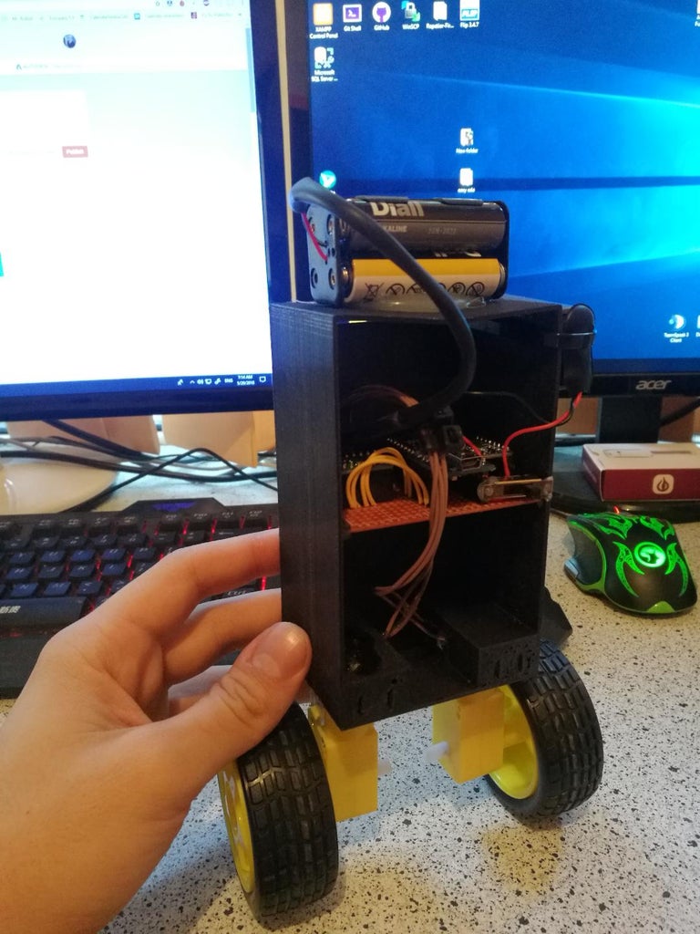
Step 6: Schematic and Build

The schematic is pretty straight forward. Connect the MPU to the arduino nano, the Driver to the nano, to the 4xAA power supply and then to the motors, connect the 9V to the nano to power it up and solder everything on the PCB.
For the frame i've created this 3d model which i've printed on a prusa i3.
Step 7: The Code
The code is using one external library that can be found here:
MPU6050_tockn.h
Initial configuration:
We need to configure our pins such way that we can send the PWM to the driver, recieve the data from the MPU and process it.
#include <MPU6050_tockn.h>

#include <Wire.h>

#include "math.h"

#define motor1FWD 6
#define motor1BCW 5
#define motor2FWD 9
#define motor2BCW 10

MPU6050 mpu(Wire);

void setup()

{
  pinMode(motor1FWD,OUTPUT);
  pinMode(motor2FWD,OUTPUT);
  pinMode(motor1BCW,OUTPUT);
  pinMode(motor2BCW,OUTPUT);

  Serial.begin(9600);
   Wire.begin();
  mpu.begin();
  //mpu.calcGyroOffsets(true);
  mpu.setGyroOffsets(-0.6, 2.18, 2.18);
}
The commented line is used for the initial configuration of the robot instead of setting the offsets manually. After you find out your offsets you can replace them in mpu.setGyroOffsets(-0.6, 2.18, 2.18);
After we define our pins and mpu variable it's time to make the sampling function which tracks the duration of each loop
#define STD_LOOP_TIME 10
int timeGoneBy = STD_LOOP_TIME;

unsigned long loopStartTime = 0;

void timekeeper() {
    timeGoneBy = millis() - loopStartTime;
    if (timeGoneBy < STD_LOOP_TIME) {
        delay(STD_LOOP_TIME - timeGoneBy);
    }

    loopStartTime = millis();
}
We also need the function that calculates the PD output based on the Kp and Kd constants and the input angle
int PIDFct(float pitch) {

   // Calculate time since last time PID was called (~10ms)
    //  - - - - - - - - - - - - - - - - - - - - - - - - - - - - - - - - -
    thisTime = millis();
    double timeChange = double(thisTime - lastTime);    // Calculate Error
    float error = targetAngle - pitch;    // Calculate our PID terms
    //  - - - - - - - - - - - - - - - - - - - - - - - - - - - - - - - - -
    float pTerm = Kp * error;
    float dTerm = Kd * (pitch - lastpitch) / timeChange;     lastpitch = pitch;
    lastTime = thisTime;   // Set PWM Value
    //  - - - - - - - - - - - - - - - - - - - - - - - - - - - - - - - - -
    float PIDValue = pTerm  - dTerm;   // Limits PID to max motor speed
    //  - - - - - - - - - - - - - - - - - - - - - - - - - - - - - - - - -
    if (PIDValue > 255) PIDValue = 255;
    else if (PIDValue < -255) PIDValue = -255;     // Return PID Output
    //  - - - - - - - - - - - - - - - - - - - - - - - - - - - - - - - - -
    return int(PIDValue);
}
The functions that are in charge with sending the signal to the motors drivers
void Back(float sign)

{
  analogWrite(motor1FWD,sign);
  analogWrite(motor2FWD,sign);
  analogWrite(motor1BCW,0);
  analogWrite(motor2BCW,0);
}
void Forw(float sign)
{
  analogWrite(motor1FWD,0);
  analogWrite(motor2FWD,0);
  analogWrite(motor1BCW,sign);
  analogWrite(motor2BCW,sign);
}
And finally the loop function where we read the angle and based on the PD computation we send PWM's to the motors.
void loop()
angle = ((1-alpha) * angle + alpha * mpu.getAngleX())-0.0003*dT++ ; motorOutput = PIDFct(angle); if(motorOutput>0) { Back(abs(motorOutput)); } else { Forw(abs(motorOutput)); } Serial.print(" "); Serial.println(angle); Serial.print(" "); timekeeper(); }
{
mpu.update();
The MPU library has it's own method mpu.getAngleX() that calculates the complementary filter. I've passed that data through a second first order filter to remove extra noise and also added a manual compensation (-0.0003 on each loop ) to compensate for the drift that the complementary filter could't fix.
All the code


