

Introduction: SelfiesBot — Twitterbot That Takes Selfies Using Rapsberry Pi


SelfiesBot is a Twitterbot that takes...Selfies! The Twitter feed for @selfiesbot is here.
SelfiesBot is a sculpture that uses a Raspberry Pi to take a photo, preview it and then post it to its Twitter account.
This Instructable will give details of the software, electronics and physical construction involved with SelfiesBot. This is by far the most complex Instructable that I've written.
Step 1: Conceptual Development


As with all of my art projects, I spent a lot of time thinking this one through.
SelfiesBot is the crown jewel of my Bot Collective — a series of Twitterbots. Each bot has a “body” (a sculptural shell) and a “brain” (a microcontroller that sends Tweets), making the collective a set of network performance art objects.
SelfiesBot takes the phenomenon of the "selfie" and puts it into an automated form. The bot takes a picture of itself...or does it? Push button controls make operate it. A mirroring effect takes place as it looks infinitely into its own preview monitor.
I discovered two things early on:
1. People like to pose next to SelfiesBot — such that the human selfies meme continues.
2. I quickly discovered that pictures alone aren't very compelling. So, I modified SelfiesBot so that it combines each photo it tweets with random text that scraped from Twitter that uses the #selfies hashtag. People don't know what the text will be, so SelfiesBot acts as a sort of roulette wheel of collaged image & text.
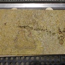
Step 2: Flowchart the Interaction

I divided the project into three stages:
Electronics
Using the GPIO, SelfiesBot has a series of buttons that let you take pictures, save them, post them and delete them.
Software
Using Python and the command-line environment, SelfiesBot interfaces with the electronics with a simple UI to let you take images, manage them and tweet them.
Fabrication
SelfiesBot is a sculpture that houses the electronics and software, hiding them.
I built the basic electronics first and then the software.
What was extremely helpful was creating this flowchart that shows the interaction of the buttons and different UI screens. It could have been easy to skip this step, but oh, was I happy to diagram in front of me when coding the interface screens in Python.
Step 3: Setting Up the Raspberry Pi

There are several things we want to do with the Raspberry Pi:
1. Basic configuration
2. Installing the GPIO
3. Making a Twitterbot
4. Making your Python Script Autostart
Fortunately, I've written Instructables for each of these steps. I deployed the Autostart code at the end, since I wanted to get the software working in the shell environment before locking myself into Autostart.
I began with Steps 1-3. I saved step 4 for the very end, after testing the timing and interaction with friends and colleagues.
Step 4: Gather Components


I used a nearly duplicate set of components as the my Black Box Timelapse — these steps are close-to-identical to my previous Instructable.
Here's the component list:
- Raspberry Pi
- Small TFT monitor, which I ordered from Adafruit for $45.
- Rechargeable 12V battery
- USB battery that outputs 2A. Currently, I'm using this one from Adafruit, which has been reliable, thought a bit heavy
- a 12V USB powered supply. Since I need to run 12V for the monitor and want 3 USB ports (wifi dongle, USB and keyboard) and because the Raspberry Pi only runs 2, a powered hub makes sense. Plus, it saves battery life for the Raspberry Pi.
- RCA male-to-male coupler
- Micro USB for running out to the battery
- Perf board with: 3-position switch, leads for recharging and GPIO.
- GPIO via the Raspberry Cobbler
* This 12V battery ended up having problems with the USB output. I was hoping to have one battery run the show, but the Raspberry Pi ended up spiking the power needs when the camera was taking a picture and then the battery would cause a voltage drop, forcing the Raspberry Pi to reboot
Step 5: Battery Charging Mechanism


The electronics portion of this Instructable isn't as well-developed as I'd like. I'm going to improve upon this in the future.
The perf board uses both a simple charging circuit for the 12V battery and two buttons for interaction control.
This brand of battery has a the same input and output jack, so I rigged up a simple mechanism which has a three-position switch. In the up position, the 12V battery supplies power to the monitor via the video cables. In the down position, it will look for the charger, as the female connector. In the neutral or middle position, no power will be active. I tie all the grounds together (video, battery, charger) and the switch will connect the positive wire of the battery to either to the video monitor, the charger or nothing. The USB battery isn't part of this circuit and has an on/off switch.
Step 6: Electronics Circuit for the Two Buttons

This is a fairly straightfoward electronics circuit. I used two buttons and two LEDs to control the menu system.
These components are covered in my Using the GPIO with the Raspberry Pi Instructable, so please read this through to figure out more on how to set up a simple pushbutton and LED with the Raspberry Pi.
(just in case, the circuit diagram is above).
Step 7: Setting Up the Camera

For the camera mount, I 3D-printed this camera holder, from a previous Instructable that I wrote and put it on a small tripod that can be wrapped around one of SelfiesBot's hands.
I would highly recommend using the PiCamera Python module for using the Raspberry Pi.
The implementation details are in my SelfiesBot GitHub repository — feel free to download it and play with it.
One thing that I did discover with using the Raspberry Pi camera module is that it takes about 250mA of power, so originally I was using a lower-grade battery and when the current would spike, the battery would drop its power to the Raspberry Pi, forcing a reboot.
Step 8: Coding in Pygame
Once I had all the basic software installed on the Raspberry Pi, the SelfiesBot code took about a day to write.
I used the Pygame environment as my interaction model, using my flow chart to navigate through the different screens for button input. The SelfiesBot GitHub repository has all the code in it.
Development was tedious, but following my interaction flowchat was critical in making this a smooth programming experience.
The LEDs simply light up when you hold one of the buttons down, so that you know the electronics circuit is actually working.
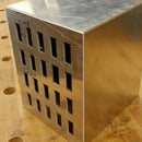
Step 9: Build the Electronics Armature


The housing for the electronics is often the trickiest part of any electronics project — and one which is usually overlooked.
The first thing I did was built out an armature for all of the electronics. This took a few iterations, some cardboard prototyping, but eventually I nailed it.
The essential components are:
1. the batteries — these have to be easily accessible so they can be recharged.
2. the Raspberry Pi — this is buried in there, but I do want to be able to sometimes pull the SD card
3. a 12V-powered USB hub that powers a wireless keyboard, the WiFi dongle and a small USB drive where the images will be stored. The little USB drive is also something I want to have access to.
4. The GPIO and the various tethered electronics coming out the back
5. Video monitor (this will end up being attached to the face) and can be detached from the rest of components in the armature.
6. Lots of cables
I wish I had better documentation of this step, since it was critical, but hopefully you get the idea. I secure the batteries with velcro. Everything else is held in by various blocks of wood. You'll see a nice photo at the end of the Instructable.
Step 10: Lasercut the Panels Armature

Based on the dimensions of the electronics armature, I came up with a second armature, which is the exoskeleton of SelfiesBot.
The electronics armature nestles into this one and can be completely removed to work/fix the electronics.
We will later attach the exterior panels to this armature.
Step 11: Armature Assembly


Using a brad nail gun, I fastened together the exoskelton armature.
Even without a jig, it ends up being fairly square, at least good enough to hold the exterior panels.
Step 12: Paint the Exterior Panels a Light Gray

I used 1/8" birch ply for the exterior faces of SelfiesBot.
I was a lot easier to paint one big panel than hand-painting many smaller ones, so I painted a gray color before laser-cutting the panel pieces I used 1 coat of primer and 2 coats of low-VOC latex paint.
I also created a base for SelfiesBot, which was a 3/8" piece of wood. I first laser-cut this and then painted this at the same time as the 1/8" wood.
Step 13: Attach Bottom Plate to Armature


I used a couple brad nails to properly tack the armature in place. Then, I attached the bottom plate to the built armature with several screws from the bottom.
Step 14: Cardboard Prototype Panels


I spent loads of time on this step. The back plate needed to fit the electronics: the buttons, two LEDs, and more. Laser-cutting cardboard was fast and cheap, so hours of iteration were-well worth it.
Step 15: Lasercut Panels


Based on the cardboard protoypes, I lasercut the panels. Since they were painted before cutting, I had to be super-careful to get the cuts right.
Step 16: Clean Edges on the Belt Sander


The edges were burnt, as always with a laser-cutter. I eventually painted these white, but I needed to reduce the burn marks, so I cleaned the edges with a belt sander. You can sand these by hand if you don't have this tool in your shop.
Step 17: Paint Edges and Touchup


I painted the edges white, first putting on a coat of primer. I also did touchups on the extra burn marks on the gray.
As you can imagine, this step took a lot longer than it looks. I soon embraced the zen of painting.
Step 18: Finished Panels


After many hours, I finished the panels. They came out great!
Step 19: Glue Screen Holder


I laser-cut a holder for the TFT monitor based on measurements with a caliper and then glued it onto the panel. I can detach the video cable at the top of the monitor or at the side of Raspberry Pi for easy removal, so that the monitor always stays nested into the face panel. The screen press-fits cleanly into the holder.
Step 20: Attach Panels


Using the brad nailer with a 5/8" nail, I methodically attached the left, side and front panels to the armature.
The white edges needed to align perfectly. This required much patience.
Step 21: Spackle Touchup


Now I had little brad nail holes everwhere. A bit of spackle and touchup paint easily fixed this.
Step 22: Magnets to Panels


The top and back panels are removable with magnets. I laser-etched holes for the magnets and press-fit them into the undersides of these two panels.
Step 23: Magnets to Armature


Putting the magnets to the armatures was more work. Using a laser-cut guide and a transfer punch, I drilled holes in the armature that align perfectly to the magnets on the panels.
Step 24: Epoxy Magnets


Then, I used a dab of epoxy to glue the magnets into the armature.
Step 25: Arm to Armature


SelfiesBot has giant arms — as you can see in the picture. I attached them with this screw-in microphone piece which has matching threads. Using a transfer punch, I marked the drill holes, drilled them out and then bolted them through.
Step 26: 3D Print the Hands


Starting with a crude sketch, I worked with Autodesk Fusion 360 expert, Taylor Stein to design these robot hands for SelfiesBot. Not only do they look great — every robot should have claw hands — but they also serve as a way to grip the flexible camera mount.
We added some detail to the fingers to give it a mechanical look and 3D printed hole for tapping threads for the gooseneck arm.
Step 27: Tap the Hands


Using a tapping kit, I tapped the 3D-printed hand to match the screw threads for a 2-foot gooseneck arm.
The arm is the same as the kind as a microphone stand. I found the 2' long version at McMaster-Carr.
Step 28: Make the Arms Detachable


The gooseneck has to be screwed in very tightly to its base, otherwise it spins too freely. This created a problem where taking the arms on and off was difficult.
The lathe came to the rescue! I made a coupler with a set screw that allows for quick attachment and detachment of the arm from the body. This took awhile, but now it is very convenient to make SelfiesBot's arms quickly removable.
Step 29: Paint Panels for the Heads

I'm going to whiz through these next several steps because they are more or less the same process as what I did for the body panels. I designed 4 different heads for SelfiesBot. You'll see just the blue happy one in the remainder of this Instructable.
Pre-paint panels for the heads before laser-cutting. Once again, I use 1/8" birch ply.
Step 30: Mask and Lasercut Face


I later panted the etched area of the face, so used green painter's tape to mask the features that I will later paint.
The rest of the panels I cut without the masking tape and these will end up forming an octagon shape.
Step 31: Touchup Face Edges


I cleaned the edges with the belt sander, then used white paint for the edges. I did touchup painting for the faces.
Step 32: Spray Paint Face


I used a primer and then all-purpose silver spray paint for the face detail. It took several coats for this to work, since the burnt wood from the laser-cutting is less than ideal for the paint.
Step 33: Touchup Face


After a light sanding, I applied touchup paint to the face of SelfiesBot.
Step 34: Build the Armature for the Head


Like with the body, the face uses an armature, which I put together with a brad nailer.
Step 35: Attach Panels to Head Armature


I carefully attached the panels of the head to the armature with the brain nailer. The crucial aspect is to get clean lines between the front of the head (the face) and its neighboring panels, since this is what will appear in every tweeted photograph by SelfiesBot.
Step 36: Spackle Head


I spackled and touched up the holes from the nailer.
Step 37: Final Electronics


The final assembly of SelfiesBot meant packing all the electronics in the body. I had barely enough room to make this fit, but it did end up working nicely. But, barely.
Step 38: Done!!


This was a long Instructable. As with my Black Box Timelapse Instructable, I spent more time documenting fabrication and less on the electronics assembly than I should have (next time, I promise).
Overall the project went great. Just about everyone loves SelfiesBot.
Lessons learned and problems:
1. Finding the right sized electronics cables was tricky. For example, I wanted a 6-inch long USB micro cable, but these were nearly impossible to track down.
2. I used a 75 cm long cable for the camera (ordered from eBay). It's very delicate and I never found a good solution for this. I have a backup cable, but there's no real strain relief for the camera cable.
3. The gooseneck arms made it a lot less portable than I like. Originally I had hoped that SelfiesBot would fit in my backpack, but the arms are bulky for easy transport. At some point, I'd like to redesign the arm mechanism to make it easier to use.
I hope this Instructable was useful
You can follow SelfiesBot here: @SelfiesBot
And you can find me (Scott Kildall) here:
www.kildall.com/blog
@kildall


