

Introduction: Serial Servo Controller W/Arduino - Control Up to 12 Servos at Once Using the Arduino and a USB Connection


There are two major parts to the application. The first part I will discuss is the firmware and hardware. This includes the Arduino and another board we will use to supply power to the servos. It's important to isolate the servo power supply from the microprocessor power in case the servos need more current than the battery can supply (imagine all 12 servos stalling at once). If the power supplies are the same you could have a brownout condition on your microprocessor depending what type of power supply you are using. I will also show you the firmware required to run this application on the Arduino.
In the second part I will discuss some simple software that will allow you to control the firmware through serial commands. This software provides an interface to the Arduino firmware to control the servos, save servo start up positions, even record a series of positions, or frames, (of all channels saved at once) to playback in sequence when desired. The software is .Net based so make sure you have the latest .Net framework installed. I will be supplying an installer and source code.
Here is a video demo of the project:
Step 1: Parts List
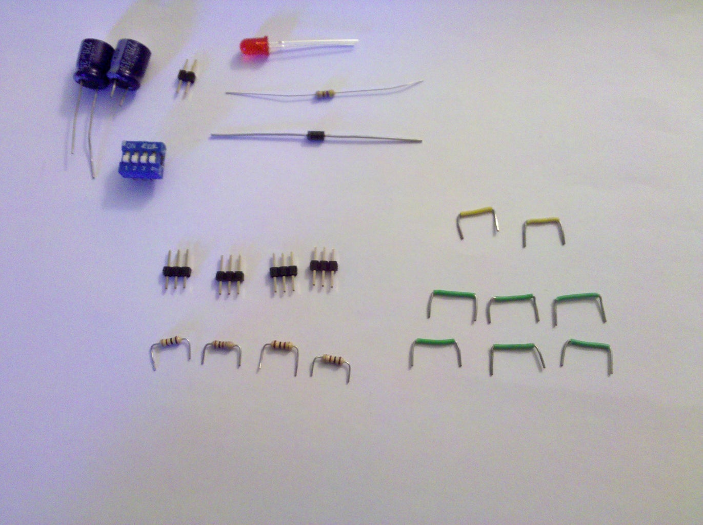

The following is a list of material and items I used for this instructable:
1x Arduino Board (Any variant that has a 328p processor)
1x BreadBoard
1x Battery 6.0-8.0Vdc (I used an 800maH LiPoly battery)
1x 1N4004 Diode
2x 220uF 35V Electrolytic Capacitors
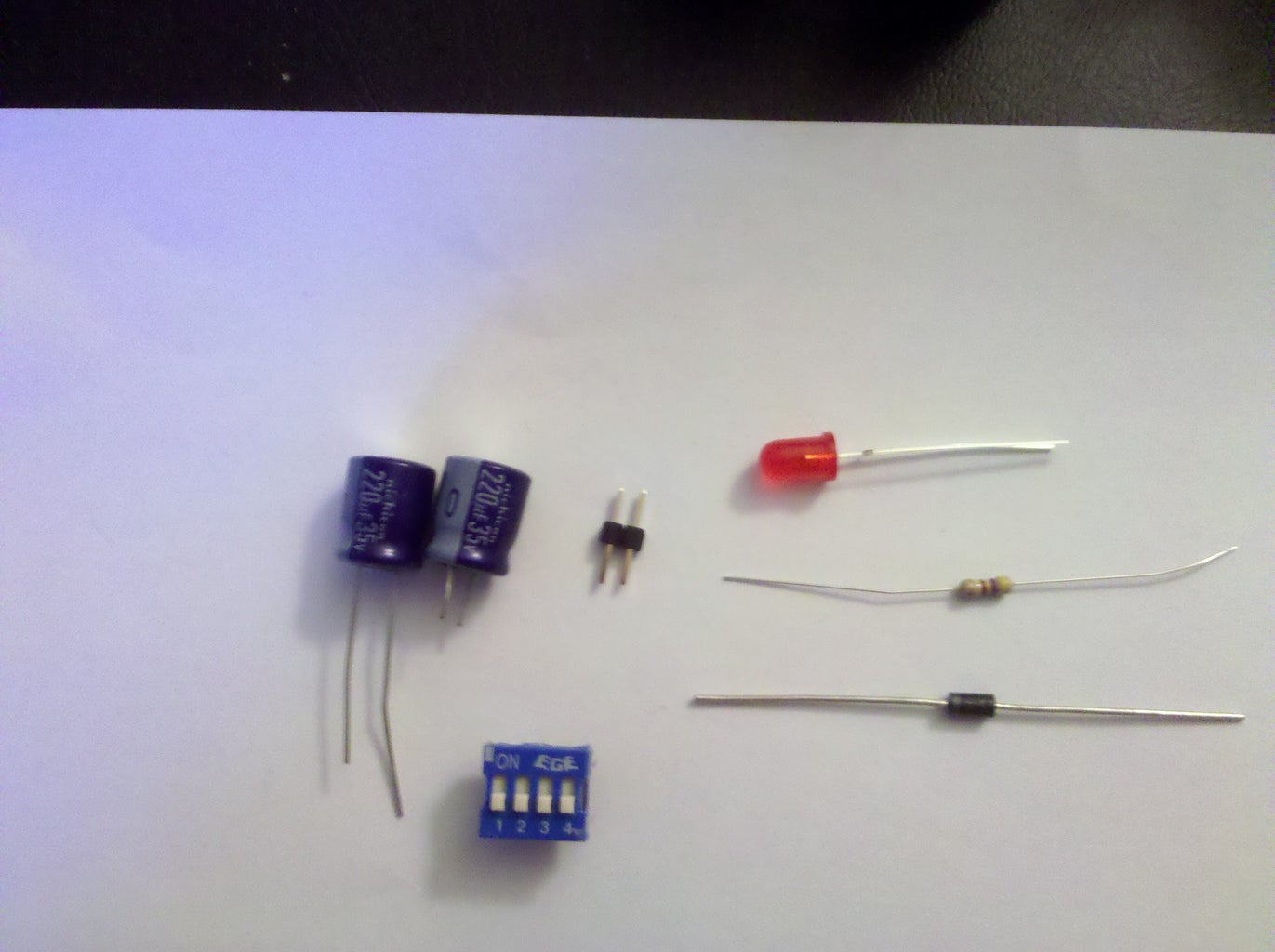
4x 3 Pin Headers (Use as many as you have servos for, I used 4 for this example but the firmware supports up to 12, just repeat)
4x 100 ohm resistors (1 for each servo. These are used for current limiting. At 3.3v the resistor limits the amount of current through the microprocessor at 3.3ma if a low impedance load is seen)
1x Small LED
1x 470 ohm resistor
1xSwitch (I used a DIP switch for simplicity)
4xHobby Servos
Various Jumper Wires
Step 2: Servo Power Supply


The servo power supply is a simple circuit I created to provide a simple and safe way to power your servos. The supply consists of a couple of capacitors to help supply extra current during high current demands on the battery, a diode to prevent reverse polarization, a convenient switch for power, and a small LED for a simple power indicator.
You will need the following in this step:
1x Switch
2x 220uF35V Electrolytic Capacitors
1x Terminal Header Connector
1x 1N4004 General Rectifier
1x Small LED
1x 470 ohm Resistor
Various Jumpers / Wires
First connect the switch, diode and terminal for the battery.
Next add the filter capacitors.
Finally add the power indicator led and current limiting resistor.
Next we will build the servo interface circuit.
Step 3: Servo / Microprocessor Interface


The servo / microprocessor interface is a simple interface designed to make it easy to hook up servos to the Arduino and apply the proper power and grounding circuitry for the servos. In this example I show a bank of 4 servos. It is easy enough to add more servos by duplicating this bank. For example, duplicate it once for 8 servos or twice for 12 servos total.
The interface to the Arduino is quite simple and consists of just a current limiting resistor. The resistor really isn't necessary but I like to play it safe and protect my Arduino whenever I can. Adding the resistor will prevent your Arduino from sourcing too much current to the control wire of the servo.
You will need the following in this step:
4x 100 ohm Resistors
4x Three Pin Terminal Headers
Various Jumpers / Wires
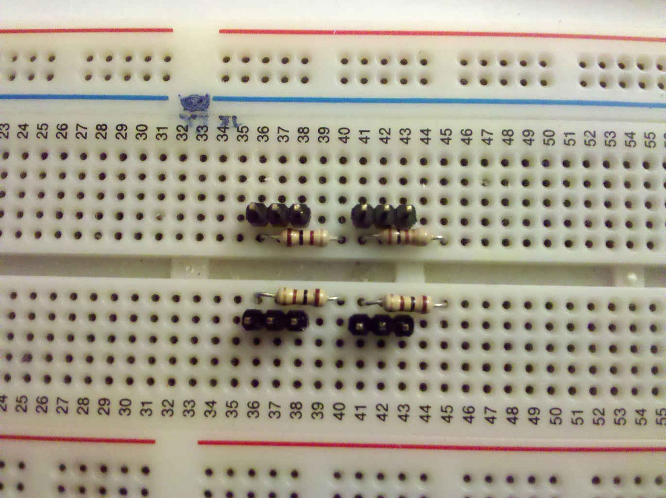
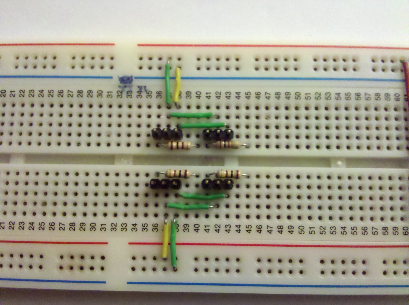
First add the resistors to the breadboard.
Next add the three pin terminal headers
Finally connect everything to proper buses (Right most pin is ground, middle is servo power)
Depending on how permanent you want it you might want to apply a liberal coat of hot glue to all the headers on the board. That will save you from having to pull the terminal headers from the connectors which they will inevitably stick to when you pull them off.
Next we upload the firmware.
Step 4: Upload Firmware

The first step before we can upload upload the firmware is to install the Arduino environment. If you haven't already installed the Arduino environment or you have an older version than v1.0 you will need to download and install the latest version. The Arduino software can be found here [http://arduino.cc/en/Main/Software].
Before you can compile the firmware, it's necessary to install the i2cEEPROM library. This library gives us access to the 24lc256 family of serial EEPROM chips. The chip is used if you want to support data storage.
Data storage is used to hold saved positions for playback, initial positions, and user custom data. I'll show a custom step at the end of this instructable that illustrates how to easily add this feature.
Note: It's not necessary to have the serial eeprom connected to your Arduino for this application to work, but it is necessary to install the library in order for you to properly upload the firmware. The firmware supports the features if the hardware is present.
Download the library as a zip here:
https://docs.google.com/open?id=0B-GOV0jkq9cROTk0ODg2ZTYtMzBkMi00ODY2LTgxZTItNTRiYWE5ODIzYTdi
The source can be found here:
https://github.com/Soshimo/I2C-Serial-EEPROM-Arduino-Library
Open an explorer window and open the folder at <Documents>\Ardunio.
Create a directory called libraries (if there isn't one already).
Unzip the contents into the libraries directory that you just created. (Note this library only works for Arduino v1.0 and later versions).
Your directory structure should look like this:
<Documents>/Arduino/libraries/i2cEEPROM
Close all Arduino windows and restart the Arduino software.
Check that the library was loaded correctly.
Navigate to the library import menu: Sketch -> Import Library.
On the list of available libraries to import you should see i2cEEPROM. If you don't see it, make sure you have the path correct as above and shut down all instances of Arduino before restarting.
Finally download the SerialServoControl sketch:
https://github.com/Soshimo/Serial-Servo-Controller-Firmware
The easiest way to get the sketch into your Arduino environment is to create a new sketch called SerialServoControl. Open the .ino file downloaded above in notepad (or your editor of choice). Copy the entire file's contents and paste into the window of the new sketch you created.
Save the sketch.
Upload the sketch to your Arduino.
Next we will hook up the Arduino to the servo controller board we built in the last two steps.
Step 5: Connecting Arduino to Servo Control Board

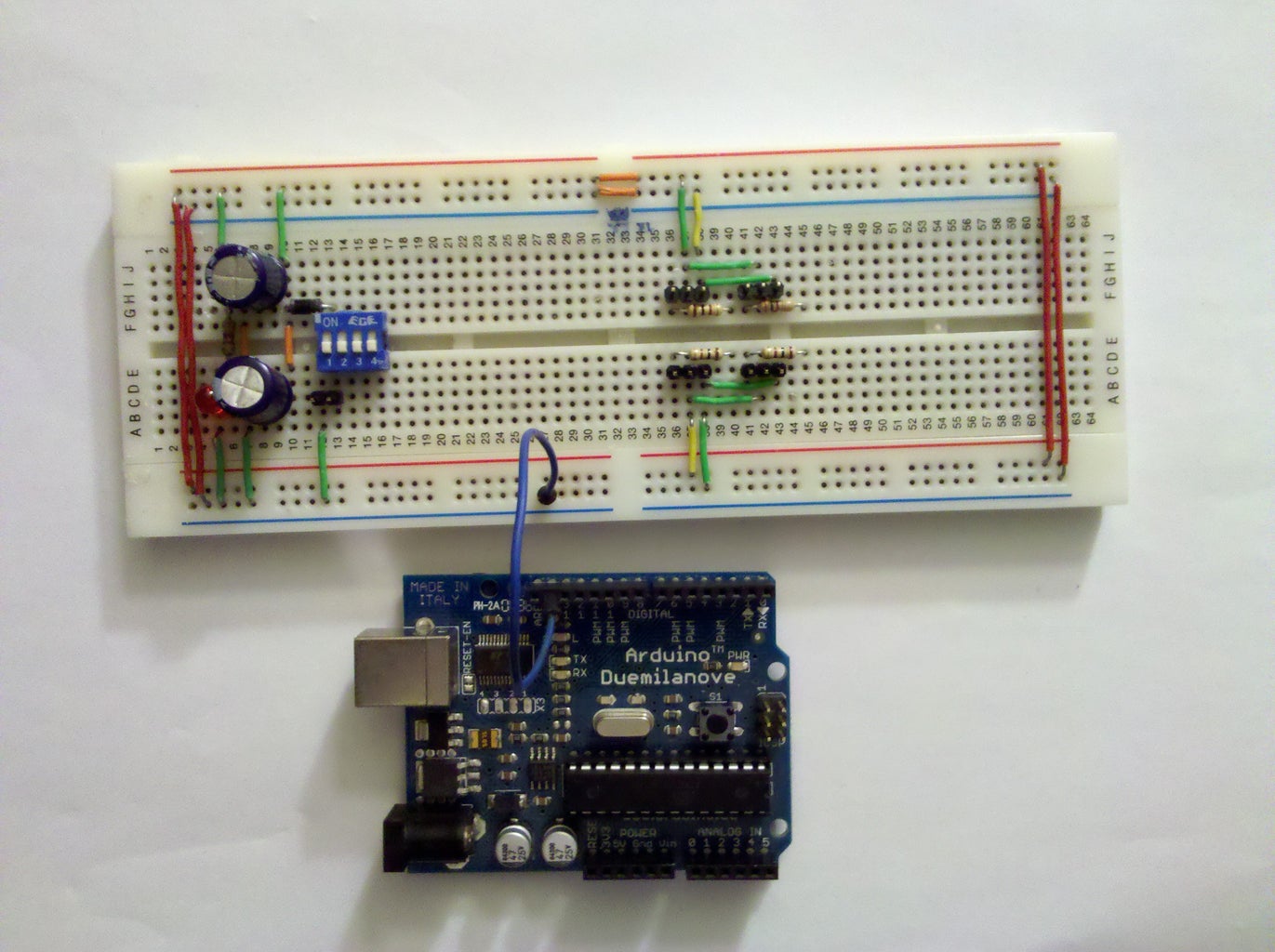


The next step is to connect the Arduino to the servo control board that we built in the last couple of steps. I am using an Arduino Duemilanove but you can use any compatible Arduino. Note that older Arduinos built on chips before the ATMega328p will not work for this demo. The ATMega168 does not have enough memory to store the program and you will not be able to run it. Basically make sure you have at least 32k memory on your device available for programming.
The electrical interface is simple. Ground must be connected between the breadboard and the Arduino The servo control pins start at digital pin 2 for channel 0, up to digital pin 13 for channel 11. Bring each pin out to the breadboard. Tie them to the current limit resistor (100 ohm resistor). Connect the servos to the terminals. Make sure you pay attention to polarity. The black wire, or ground, is always on the right.
The next step is to install the serial control software.
Step 6: Installing and Running the Software

In the end I went with simplicity and created an installer for the Serial Servo Control software. The software requires .Net Framework 3.5sp1 or better (the latest version of the framework will be fine). I'll also provide source code for modification.
The program is simple and the interface is crude and dated but it works. You can control one of 12 different channels (0-11) with a slider, numeric up/down, or directly entering the value you want. The values are in degrees and represent the servo position to move to. In this version the servo traverses at it's fastest speed but I'll add ramping in a later version.
Here is the link to the installer (Admin Rights Required):
https://docs.google.com/open?id=0B-GOV0jkq9cRMDY4YWE3ZjAtNGU1YS00MDRiLTg3NzAtZjA2YzQ0ZDMyZWYx
Here is the link to the source code:
https://github.com/Soshimo/Serial-Servo-Controller
I'm not going to support modifying or building the source code so you are on your own for that. One caveat, it requires the Windows XML Installer SDK to be installed on your machine. If you don't have that installed you can just remove the installer project from the solution. It's built for Visual Studio 2008 but can be upgraded to 2010 with no problem. The project requires .Net framework version 3.5sp1.
Troubleshooting:
Do you see the Arduino COM port in the list of COM ports to connect to?
If no, make sure you have the correct Arduino drivers installed and that the board is powered on.
When you send commands to the firmware do you see any errors in the terminal window?
Sometimes the errors can help you pin point the problem.
Do some of the servos move but not others?
Check polarity on the servo cables, make sure the connection is secure - sometimes they can work loose if you haven't hot glued the terminals down (or otherwise secured them).
Can you reset the terminal from the Terminal -> Reset menu?
Make sure the USB cable is connected to the Arduino USB port. The firmware uses the hardware UART.
Finally, if nothing is working and no feedback is given from the terminal window check all your electrical connections. Make sure the servo cables are connected correctly. Invest in a DMM if you don't already have one - you can find usable ones for under $50. Check voltages with power applied. Make sure you have at least 5V going to the servos or they won't move properly. Check ground connections on the board. Make sure all voltages are equal across all ground points. Finally, remove power from the circuit and check continuity. IMPORTANT! Make sure you remove power before checking continuity. You could damage your DMM, board, Arduino, or yourself otherwise.
I take no respsonbility, niether expressed nor implied for anything you may do while constructing or using this project. This project is MIT licensed [http://www.opensource.org/licenses/mit-license.php] so you are free to use it and modify it at will. I only request that you keep any attributes. Have fun!
Step 7: [Optional] Add Serial EEPROM for Saving Values
![[Optional] Add Serial EEPROM for Saving Values](https://content.instructables.com/FUP/BSHP/GX0ZVQI8/FUPBSHPGX0ZVQI8.jpg?auto=webp&fit=bounds&frame=1&height=1024&width=1024auto=webp&frame=1&height=300)
![[Optional] Add Serial EEPROM for Saving Values](https://content.instructables.com/FQZ/UD4F/GX0ZVRLX/FQZUD4FGX0ZVRLX.jpg?auto=webp&fit=bounds&frame=1auto=webp&frame=1&height=300)
![[Optional] Add Serial EEPROM for Saving Values](https://content.instructables.com/F33/TKIP/GX10CHFP/F33TKIPGX10CHFP.jpg?auto=webp&fit=bounds&frame=1auto=webp&frame=1&height=300)
![[Optional] Add Serial EEPROM for Saving Values](https://content.instructables.com/F7M/OPGD/GX106MUA/F7MOPGDGX106MUA.jpg?auto=webp&fit=bounds&frame=1auto=webp&frame=1&height=300)
![[Optional] Add Serial EEPROM for Saving Values](https://content.instructables.com/FSE/HBU8/GX10UIR6/FSEHBU8GX10UIR6.jpg?auto=webp&fit=bounds&frame=1auto=webp&frame=1&height=300)
![[Optional] Add Serial EEPROM for Saving Values](https://content.instructables.com/F7G/7X7Q/GX22TFUK/F7G7X7QGX22TFUK.jpg?auto=webp&fit=bounds&frame=1auto=webp&frame=1&height=300)
![[Optional] Add Serial EEPROM for Saving Values](https://content.instructables.com/FC6/M53V/GX22TFUM/FC6M53VGX22TFUM.jpg?auto=webp&fit=bounds&frame=1auto=webp&frame=1&height=300)
![[Optional] Add Serial EEPROM for Saving Values](https://content.instructables.com/F0L/0C7N/GX1N7XUL/F0L0C7NGX1N7XUL.jpg?auto=webp&fit=bounds&frame=1auto=webp&frame=1&height=300)
This step I'll show you how to quickly add some storage capacity to our application. We will use the Microchip 24lc256 serial EEPROM to give us 256k bytes of user data storage. This includes servo set positions as well as frame playback (the software supports up to 10 frames). It also includes about 200kb of user data storage for the application do do anything you want. You can store a history of positions for a histogram later or whatever your imagination can think of!
The parts list is simple:
2 x4.7k ohm resistors. [The 328p does have built in pullups on the SDA/SCL lines but if you want to chain multiple devices pull ups are recommended. The Microchip datasheet recommends 4.7k ohm and the Atmel recommends not more that 10k ohm resistance, so I went with the datasheet]
1x Microchip 24LC256 IC - Low power serial (I2C) EEPROM chip.
Various jumpers
First add the IC to the board. Pay attention to the orientation of the chip. The front of the chip has a slight indentation.
Connect Vss to the breadboard ground.
Connect A0-A2 of the Serial EEPROM to ground.
Connect Vcc to the Vcc tie point. DO NOT connect to the breadboard power rail. You will most likely damage your chip.
Connect the pull up resistors (4.7k ohm) from SDA/SCL to the tie point.
Connect Arduino 5V (3.3V may work as well, check the datasheet for the IC you are using) to the tie point.
Connect Arduino ground to the breadboard ground (if you have not already done so in a previous step).
Connect Arduino Analog In 4 (SDA) to the Serial EEPROM SDA (pin 5)
Connect Arduino Analog In 5 (SCL) to the Serial EEPROM SCL (pin 6)

Participated in the
ShopBot Challenge


