

Introduction: Simple IOT Project Using ESP8266 and MQTT Protocol


In this tutorial I will share this project with you , a simple
IOT application based on MQTT protocol and Adafruit.io broker.
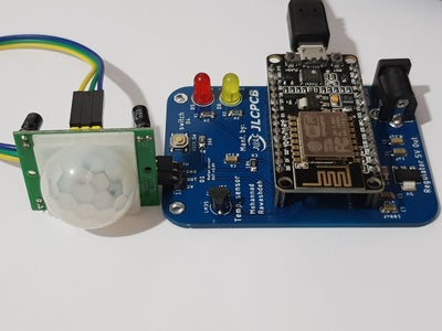
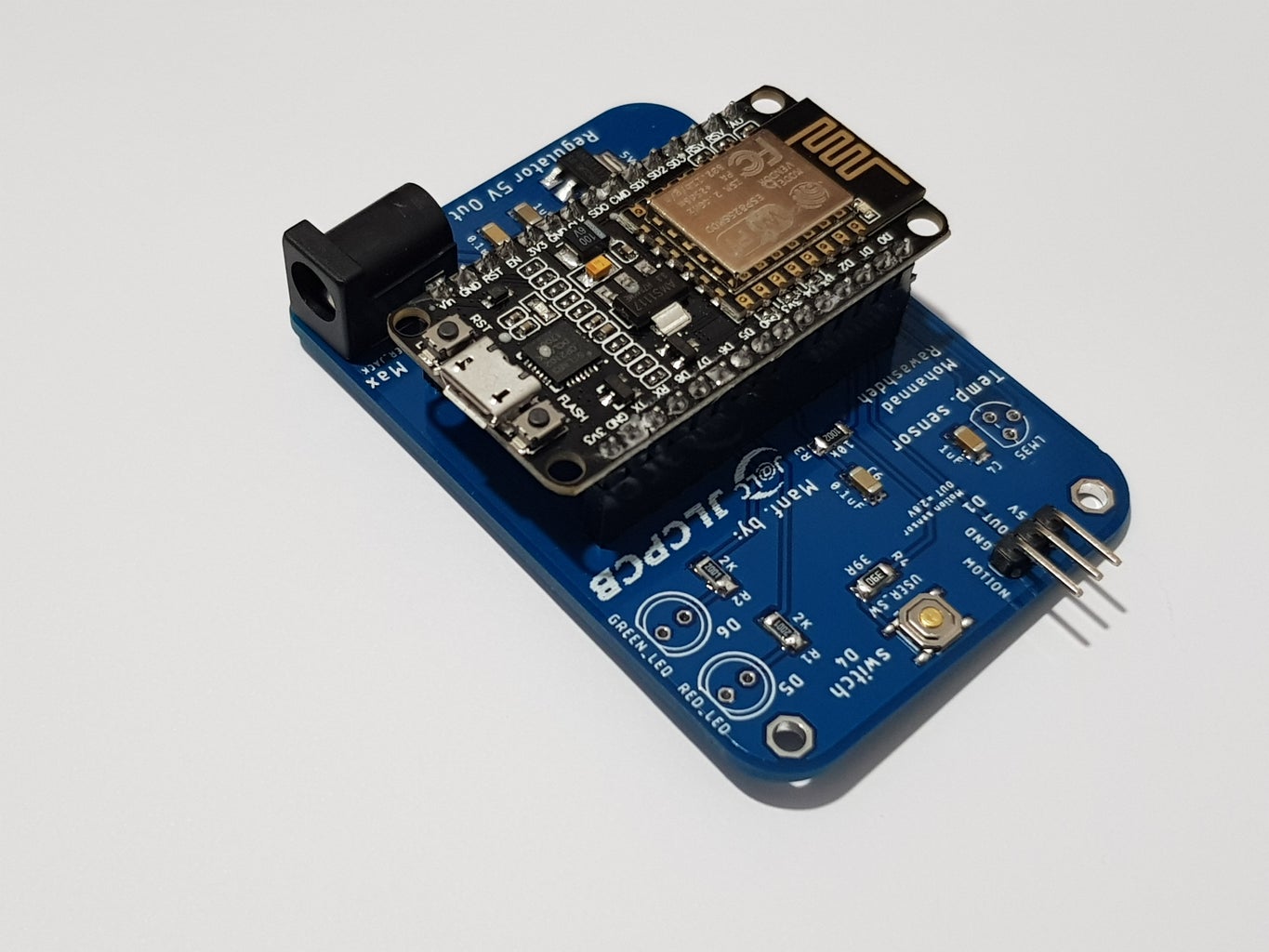
For this project I designed a PCB circuit so you can solder all the components on this board.
What I’m going to to:
- Control LED on/off.
- read a LM35 Temperature sensor value.
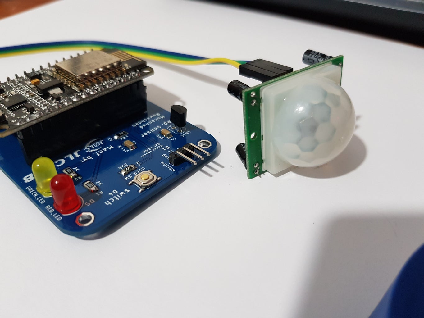
- read a Motion sensor value.
all these component will be connected to ESP8266 nodemcu 1.0v and to Adafruit.io dashboard so I can see read all the sensors and control LED using this dashboard , and later on I will show you how to design your own dashboard.
Step 1: What Is MQTT ?


mqtt is an extremely simple and lightweight messaging protocol,based on lightweight publish/subscribe messaging transport.
in our case A sensor connected to ESP8266 will publish a value let's say a temperature value , and user form a smart phone or a computer can read this value by subscribing to this value
also the user can publish a value for example to control LED and the ESP8266 need to subscribe to this value in order to read it.
a broker used to manage and handle all these messages between all subscribed clients in our case we will use Adafruit.io to be our broker.
Step 2: Schematic and PCB Layout and Part List

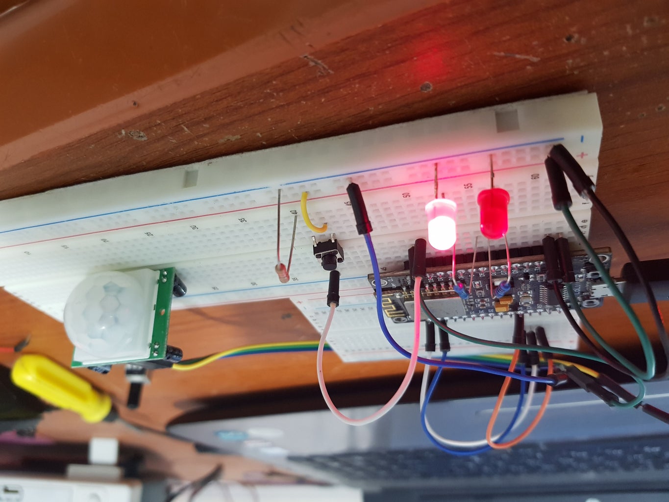


To ensure everything is working as I expected I built my circuit on a breadboard and tested with this code
The LED connected to D6 must turn on if you press the button.
The LED connected to D5 must turn on if a motion detected.
If you open the serial you must be able to read a temperature value.
Then I transferred this project to a schematic on Eagle as you can see on the images below , I provided a schematic and PCB layout if you want to modify it.
Download the Eagle files and Gerber file from Here
Notice:
I used a regulator AMS1117-5V to feed the Main nodemcu Board and Motion sensor, you can ignore this circuit by powering the circuit through nodemcu USB Port.
I recommend you to power on the LM35 from 5V rather than 3.3V power source , the result is not accurate with 3.3V all the times
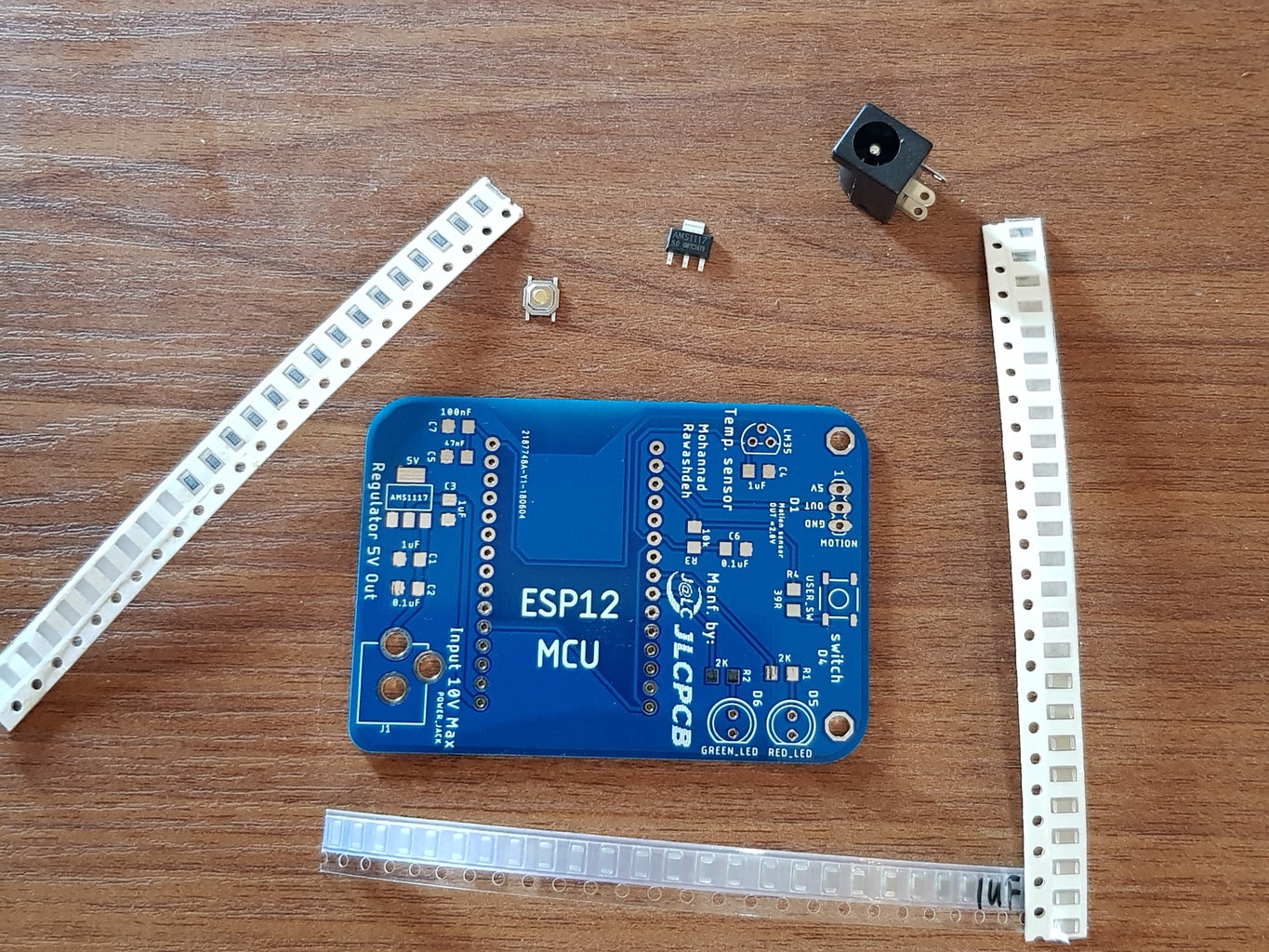
This is the part list we need for this board.
- Capacitor smd 1206 1uF * 3Pcs (Link)
- Capacitor smd 1206 0.1uF * 2Pcs (Link)
- Capacitor smd 1206 47nF * 1Pcs (Link)
- Resistor smd 1206 2K * 2Pcs (link)
- Resistor smd 1206 10K * 1Pcs (link)
- Resistor smd 1206 39 ohm * 1Pcs (link)
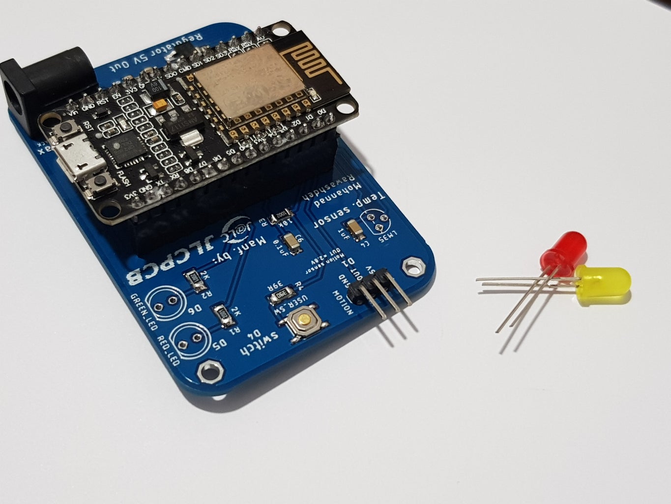
- LED 5MM * 2PCs (link)
- Regulator AMS1117- 5V SOT223 (link)
- Motion sensor PIR (link)
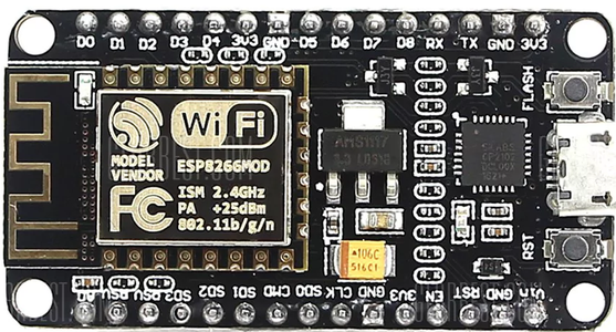
- NODEMCU ESP-12E 1.0V (link)
- DC jack 2.1mm (link)
- Button smd 4 pin (link)
- LM35 Sensor (link)
Step 3: Ordering PCB and Solder the Components


You need a gerber files if you want to transfer your design
to a real board , I ordered my PCB from a chines website called JLCPCB (visit it from here).
To order your PCB:
1- Go to JLCPCB website.
2- Create an account for you
3- From home page click buy now
4- Click on PCB tab and upload your gerber files, you can see a preview for your design
5- Select the other PCB option, number of layer , Silkscreen color , etc.. and complete your order
Step 4: Soldering the Components


Soldering technique could be different from one to another , depend on your setup and equipment you have .
I used a solder paste and I place all the components together and then solder them using a heat plate
Always solder SMD components first and check if you solder them well before you solder any THT components (Like Pin headers ).
For NodeMCU you can solder it directly to the board but since I want to make it swappable I soldered a female Header first and then mount NodeMCU on it.
when you solder the LED be careful to the anode and cathode pin position , otherwise the led will not working.
watch the video to see the procedure .
Step 5: Arduino Codes


first you need to check if you solder all the components together correctly by uploading this test code.
you can always download the code from github
//******************** code start here ************************
<p>/*<br> * written by : Mohannad Rawashdeh
 */
const int LED_D5=14;
const int LED_D6=12;
const int ButtonPin=4;
const int MotionPin=5;
const int LM35Pin=A0;
unsigned long previousTimer1 ,currentTimer1;
unsigned long previousTimer2 ,currentTimer2;
const unsigned long timer1=500;
const unsigned long timer2=50;
// the setup function runs once when you press reset or power the board
void setup() {
  // initialize digital pin LED_BUILTIN as an output.
  pinMode(LED_D5, OUTPUT);
  pinMode(LED_D6, OUTPUT);
  pinMode(ButtonPin, INPUT);
  pinMode(LM35Pin, INPUT);
  pinMode(MotionPin, INPUT);
  Serial.begin(9600);
}</p><p>// the loop function runs over and over again forever
void loop()
{
testFunctionality();
}</p><p>void testFunctionality()
{
  currentTimer1= millis();
  currentTimer2=currentTimer1;
  if (currentTimer1 - previousTimer1 >= timer1)
  {
   previousTimer1= currentTimer1;
   int lm35=analogRead(LM35Pin);
   float temp=(float)lm35*0.33;
   Serial.print((int)temp);
   Serial.println(" c");
  }
  if (currentTimer2 - previousTimer2 >= timer2)
  {
   previousTimer2= currentTimer2;
  bool buttonis=digitalRead(ButtonPin);
  bool motionis=digitalRead(MotionPin);
  digitalWrite(LED_D5, motionis);
  digitalWrite(LED_D6, buttonis);
  }
}</p>
//********************* code end here ************************
then you can upload the MQTT_adafruit_project code "you need to modify a couple of things to connect it to your dashboard" like you AIO key and username and your wifi network SSID and Password
download the Code from Here
also you need to downloadadafruit_mqtt library to run this code
<p>/*<br> * written by : Mohannad Rawashdeh
 */
#include
#include "Adafruit_MQTT.h"
#include "Adafruit_MQTT_Client.h"
#define WLAN_SSID       "Your WiFi_network"
#define WLAN_PASS       "passowrd"
#define AIO_SERVER      "io.adafruit.com"
#define AIO_SERVERPORT  1883                   // use 8883 for SSL
#define AIO_USERNAME    "your_username"
#define AIO_KEY         "AIO_Keys"</p><p>// Create an ESP8266 WiFiClient class to connect to the MQTT server.
WiFiClient client;
// Setup the MQTT client class by passing in the WiFi client and MQTT server and login details.
Adafruit_MQTT_Client mqtt(&client, AIO_SERVER, AIO_SERVERPORT, AIO_USERNAME, AIO_KEY);
/*
 * written by : Mohannad Rawashdeh
 */
const int LM35Pin=A0;
const int LED_D5=14;
const int LED_D6=12;
const int ButtonPin=4;
const int MotionPin=5;
/****************************** Feeds ***************************************</p><p>/ Setup a feed called 'photocell' for publishing.
// Notice MQTT paths for AIO follow the form: /feeds/
Adafruit_MQTT_Publish lm35 = Adafruit_MQTT_Publish(&mqtt, AIO_USERNAME "/feeds/lm35");
Adafruit_MQTT_Publish motionsensor = Adafruit_MQTT_Publish(&mqtt, AIO_USERNAME "/feeds/motionsensor");
//Adafruit_MQTT_Publish button = Adafruit_MQTT_Publish(&mqtt, AIO_USERNAME "/feeds/button");
// Setup a feed called
Adafruit_MQTT_Subscribe redled = Adafruit_MQTT_Subscribe(&mqtt, AIO_USERNAME "/feeds/redled");
Adafruit_MQTT_Subscribe yellowled = Adafruit_MQTT_Subscribe(&mqtt, AIO_USERNAME "/feeds/yellowled");</p><p>/*************************** Sketch Code ************************************</p><p>/ Bug workaround for Arduino 1.6.6, it seems to need a function declaration
// for some reason (only affects ESP8266, likely an arduino-builder bug).
void MQTT_connect();</p><p>void setup() {
  Serial.begin(115200);
  pinMode(LED_D5, OUTPUT);
  pinMode(LED_D6, OUTPUT);
  pinMode(ButtonPin, INPUT);
  pinMode(LM35Pin, INPUT);
  pinMode(MotionPin, INPUT);
  delay(10);</p><p>  Serial.println(F("MQTT Test "));</p><p>  // Connect to WiFi access point.
    Serial.println(); Serial.println();
    Serial.print("Connecting to ");
    Serial.println(WLAN_SSID);</p><p>  WiFi.begin(WLAN_SSID, WLAN_PASS);
  while (WiFi.status() != WL_CONNECTED) {
    delay(500);
    Serial.print(".");
  }
  Serial.println();</p><p>  Serial.println("WiFi connected");
  Serial.println("IP address: "); Serial.println(WiFi.localIP());</p><p>  // Setup MQTT subscription for onoff feed.
  mqtt.subscribe(&redled);
  mqtt.subscribe(&yellowled);

}</p><p>byte x=0;</p><p>void loop() {
  // Ensure the connection to the MQTT server is alive (this will make the first
  // connection and automatically reconnect when disconnected).  See the MQTT_connect
  // function definition further below.
  MQTT_connect();</p><p>  // this is our 'wait for incoming subscription packets' busy subloop
  // try to spend your time here</p><p>  Adafruit_MQTT_Subscribe *subscription;
  while ((subscription = mqtt.readSubscription(5000))) {
    if (subscription == &redled) {
      if(redled.lastread[0]=='0'){digitalWrite(LED_D5, 0);}
      if(redled.lastread[0]=='1'){digitalWrite(LED_D5, 1);}
    //  Serial.print(F("Got Red LED: "));
    //  Serial.println((char *)redled.lastread);
    }
    if (subscription == &yellowled) {
      if(yellowled.lastread[0]=='0'){digitalWrite(LED_D6, 0);}
      if(yellowled.lastread[0]=='1'){digitalWrite(LED_D6, 1);}
    //  Serial.print(F("Got yellow LED: "));
    //  Serial.println((char *)yellowled.lastread);
    }
  }
  // Now we can publish stuff!
   int lm35_Val=analogRead(LM35Pin);
   float temp=(float)lm35_Val*0.33;</p><p> // Serial.print(F("\nSending LM35 val "));
//   Serial.print((int)temp);
 //  Serial.print(" C ..");
  if (! lm35.publish((int)temp)) {
    Serial.println(F("lm35 Failed"));
  } else {
    Serial.println(F("lm35 OK!"));
  }
  int Motionread=digitalRead(MotionPin);
 //   Serial.print(F("\nSending Motion val "));
  if (! motionsensor.publish(Motionread)) {
    Serial.println(F("motion Failed"));
  } else {
    Serial.println(F("motion OK!"));
  }
  // ping the server to keep the mqtt connection alive
  // NOT required if you are publishing once every KEEPALIVE seconds
  /*
  if(! mqtt.ping()) {
    mqtt.disconnect();
  }
  */
}</p><p>// Function to connect and reconnect as necessary to the MQTT server.
// Should be called in the loop function and it will take care if connecting.
void MQTT_connect() {
  int8_t ret;</p><p>  // Stop if already connected.
  if (mqtt.connected()) {
    return;
  }</p><p>  Serial.print("Connecting to MQTT... ");</p><p>  uint8_t retries = 3;
  while ((ret = mqtt.connect()) != 0) { // connect will return 0 for connected
       Serial.println(mqtt.connectErrorString(ret));
       Serial.println("Retrying MQTT connection in 5 seconds...");
       mqtt.disconnect();
       delay(5000);  // wait 3 seconds
       retries--;
       if (retries == 0) {
         // basically die and wait for WDT to reset me
         while (1);
       }
  }
  Serial.println("MQTT Connected!");
}</p>
in the next step we will take a look at adafruit.io dashboard
Step 6: Adafruit.io Dashboard


- first you to create a free account for you onadafruit.io website.
- then by going to Dashboard you can go to ( Action ) and select " create new dashboard ".
- give it a name and click create.
- once you create your dashboard , go to " create new block "
- choose the type of block you want to use like toggle , slider , color ... etc then click next
- you need to connect this block to a feed , you can create your feed first then connect it to the block "see the forth picture"
- then you need to setup the block setting , like name , and the value this block will accept (Maximum and minimum value) or the value this block will return if you press it/change it (like returning 1 or 0 if you press the toggle)
- to connect the block to your code , you need to go to feed panel , and click the block name
- go to feed information and you will see the name of your feed , copy this name and paste it inside your arduino code (see the pictures to learn more).
Step 7: Full Video to Summarize Everything
You can watch this Video to give you a full understanding for this project


